Conveyer system

a conveyer and system technology, applied in the direction of thin material handling, loading/unloading, article separation, etc., can solve the problems of degrading the use efficiency of the semiconductor production device, and achieve the effect of easy replacement of the carrier

Active Publication Date: 2013-01-08
SINFONIA TECHNOLOGY CO LTD
View PDF15 Cites 11 Cited by
  • Summary
  • Abstract
  • Description
  • Claims
  • Application Information

AI Technical Summary

Benefits of technology

[0004]It is possible to house up to about 25 semiconductor substrates in one FOUP, for example, and there is a tendency in recent years that each of various semiconductors is produced in a small number. Along with this, a FOUP actually houses not more than a several semiconductor substrates in many cases. Accordingly, time spent for processing on the semiconductor substrates housed in one FOUP by a semiconductor production device is reduced. Therefore, conveying frequency of the FOUP is increased to increase time between the completion of processing on semiconductor substrates housed in one FOUP by a semiconductor production device and the start of processing on the semiconductor substrates housed in the next FOUP even with the structure of providing the two load ports for one semiconductor production device. As a result, use efficiency of the semiconductor production device is degraded. It is possible to maintain a high semiconductor production device use efficiency by increasing the number of load ports for one isolated space in JP-A-2003-318244. However, in this case, it is necessary to increase the number of conveyer robots with an increasing number of load ports or to move the conveyer robots along the plural load ports. With such constitution, a space in which the conveyer robots are disposed, i.e. the isolated space, is increased in size to allow contaminants to easily enter the isolated space.
[0005]An object of this invention is to provide a conveyer system capable of improving a use efficiency of semiconductor production device without increasing the number of load ports.

Problems solved by technology

As a result, use efficiency of the semiconductor production device is degraded.

Method used


Image

  • Conveyer system
  • Conveyer system
  • Conveyer system

Examples


first embodiment

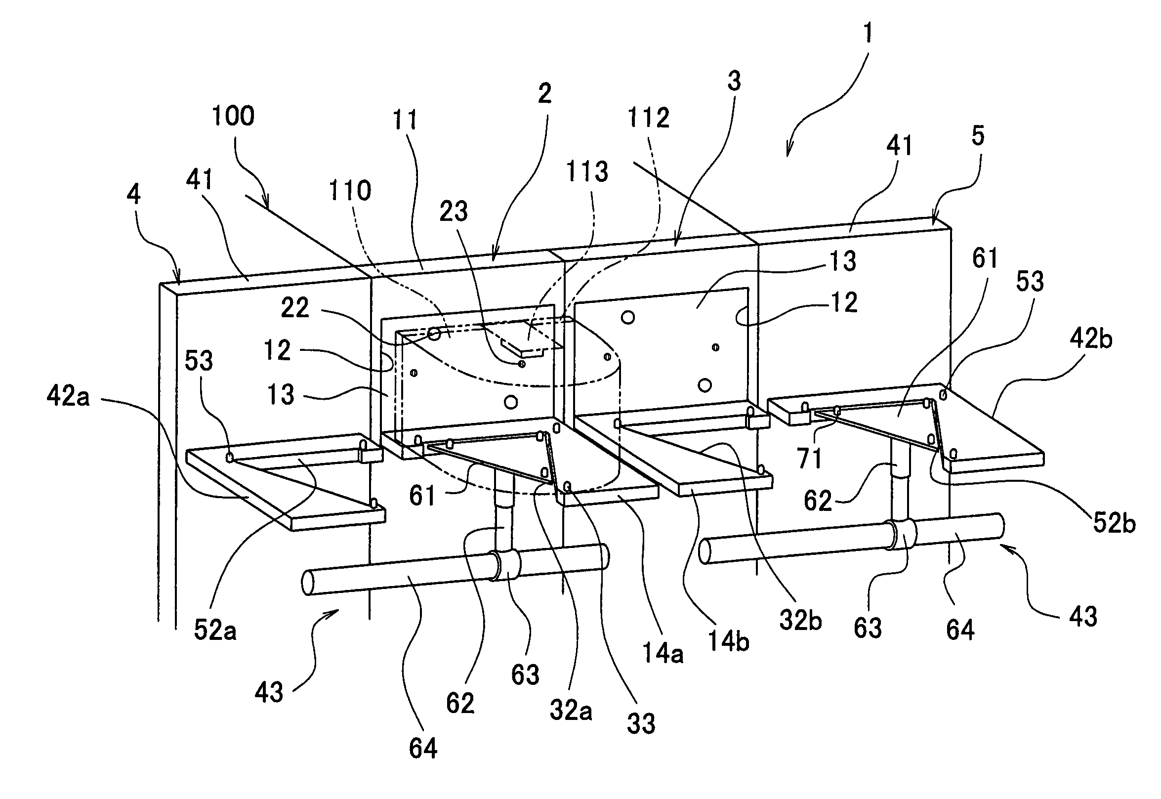
[0070]FIG. 1 is a schematic perspective view showing a conveyer system according to the first embodiment of this invention. As shown in FIG. 1, a conveyer system 1 has two load ports 2 and 3 and two relay units 4 and 5.

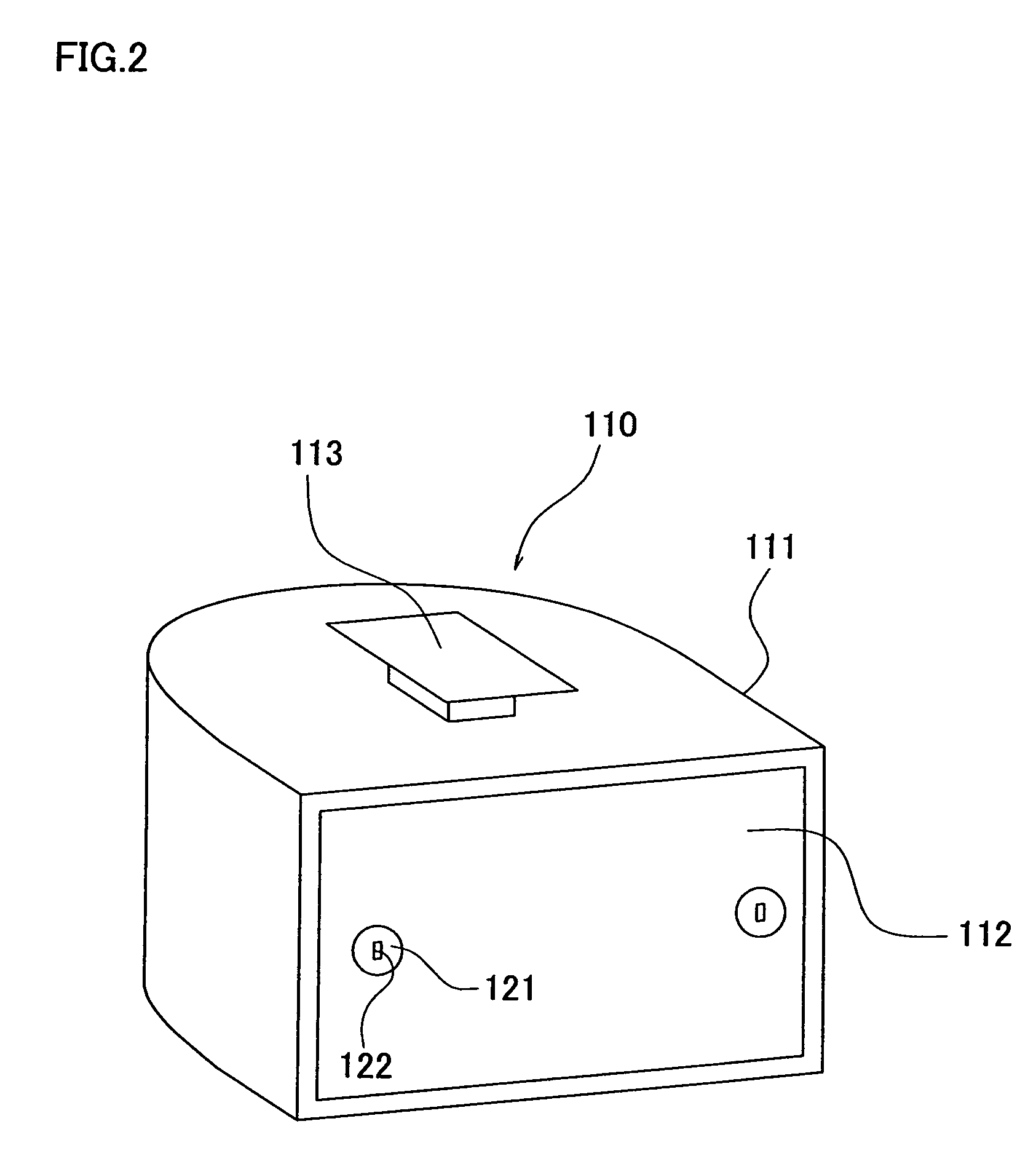
[0071]Before describing each parts of the conveyer system 1, a FOUP 110 conveyed by the conveyer system 1 will be described. FIG. 2 is a schematic perspective view showing the FOUP 110. FIG. 3A is a diagram showing FIG. 2 as viewed from the front, showing a state in which a cover 112 to be described later in this specification is fixed to a main body 111. FIG. 3B is a diagram showing FIG. 2 as viewed from the front showing a state where the fixation of the cover 112 to the main body 111 is released. FIG. 4 is a diagram showing a state in which the cover 112 is detached in FIG. 3A or 3B. FIG. 5 is a diagram showing a bottom surface of the FOUP 110.

[0072]As shown in FIGS. 2 to 5, the FOUP 110 has the main body 111, the cover 112, a flange 113, three positioning holes 11...

second embodiment

[0118]Hereinafter, the second embodiment will be described. Note that features of the second embodiment that are different from those of the first embodiment will be described, and descriptions on structures same as those of the first embodiment will be omitted as required.

[0119]FIG. 10 is a schematic block diagram showing the second embodiment, which corresponds to FIG. 1. FIG. 11 is a front view showing the second embodiment, which corresponds to FIG. 7. As shown in FIGS. 10 and 11, in a conveyer system 201 according to the second embodiment, a gap is defined between the load port 2 and the relay unit 4, and a gap is defined between the load port 3 and the relay unit 5. Further, in the conveyer system 201, conveyer devices (second conveyer devices) 80a and 80b are provided between the load port 2 and the relay unit 4 and between the load port 3 and the relay unit 5 besides structures same as those of the first embodiment.

[0120]The conveyer device 80a has a platform (forth platform...

third embodiment

[0139]Hereinafter, a third embodiment according to this invention will be described. Note that since only a part of the third embodiment is different from the first embodiment, the part that is different from the first embodiment will be described, and descriptions on the parts same as the first embodiment will be omitted as required.

[0140]FIG. 14 is a plan view corresponding to FIG. 6 in the third embodiment. As shown in FIG. 14, a conveyer system of the third embodiment has a structure wherein platforms 314a and 314b, platforms 342a and 342b, and two platforms 361 are provided in place of the platforms 14a and 14b, the platforms 42a and 42b, and the two platforms 61. And these are respectively at positions where the platforms 14a and 14b, the platforms 42a and 42b, and the two platforms 61 (see FIG. 1) are provided in the conveyer system 1 (see FIG. 1) of the first embodiment.

[0141]FIGS. 15A to 15D are plan views in which 361 provided corresponding to the platforms 314a and 314b o...


PUM


Abstract

An OHT conveyer vehicle places a FOUP on first and second on platforms. A third platform can move to a position overlapping with the first and second platform by a moving device, and then to a position at which an upper surface of the third platform is above upper surfaces of the first and second platforms by an elevation device. Therefore, the FOUP is placed on the third platform. Subsequently, the third platform can move to a position overlapping with fourth and fifth platforms by the moving device, and then to a position at which the third platform is lower than the fourth and fifth platforms by the elevation device. Therefore, the FOUP is placed on the fourth and fifth platforms.

Description

TECHNICAL FIELD[0001]This invention relates to a conveyer system for conveying a carrier to a load port.BACKGROUND ART[0002]Semiconductor production devices performing process steps for producing semiconductors are disposed inside a isolated space that is isolated from the outside and remarkably reduced in dust for the purpose of preventing adhesion of dust to a semiconductor substrate. In order to prevent the dust adhesion to semiconductor substrate, the semiconductor substrate is conveyed between the semiconductor production devices by an OHT conveyer vehicle in a state where the semiconductor substrate is housed in a carrier such as a FOUP that has a housing space for housing the semiconductor substrate in its internal part. A load port capable of providing communication between the isolated space and the outside is provided on a wall defining the isolated space, and the semiconductor substrate is delivered between the FOUP and the semiconductor production devices by the load por...

Claims


Application Information

Patent Timeline
Patent Type & Authority Patents(United States)
IPC IPC(8): B65H1/00
CPCH01L21/67763H01L21/67772H01L21/67775
Inventor MIZOKAWA, TAKUMIOCHIAI, MITSUTOSHI
Owner SINFONIA TECHNOLOGY CO LTD
Why Eureka
Try Eureka