
Method and system for layer-2 pseudo-wire rapid-deployment service over unknown internet protocol networks

a pseudo-wire and internet protocol technology, applied in the field of digital telecommunications, can solve problems such as frame collisions, data link protocols without acknowledgments, and transfer can be reliable or unreliabl

Active Publication Date: 2013-01-08
YR20 GROUP
View PDF18 Cites 6 Cited by
  • Summary
  • Abstract
  • Description
  • Claims
  • Application Information

AI Technical Summary

Benefits of technology

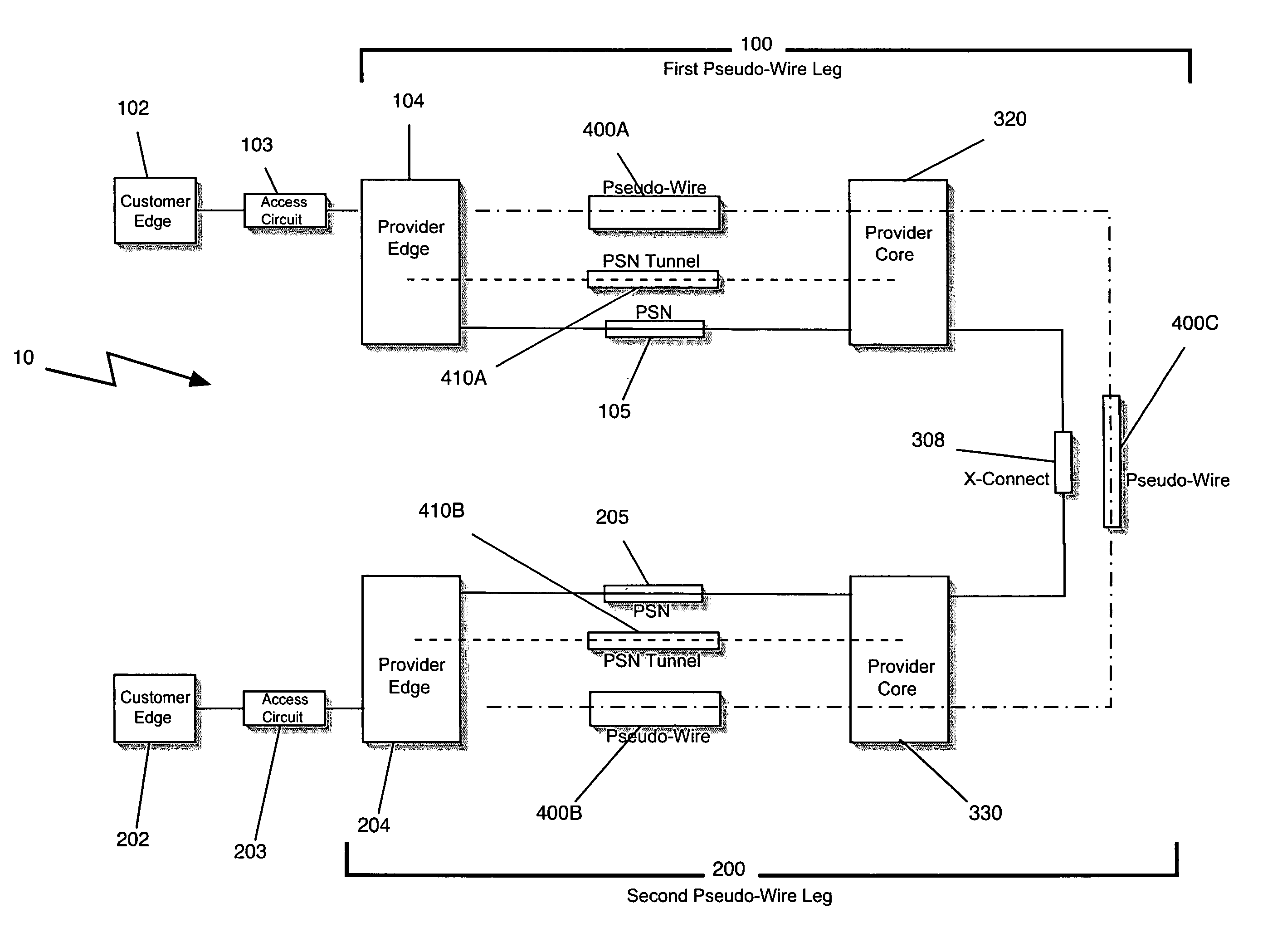
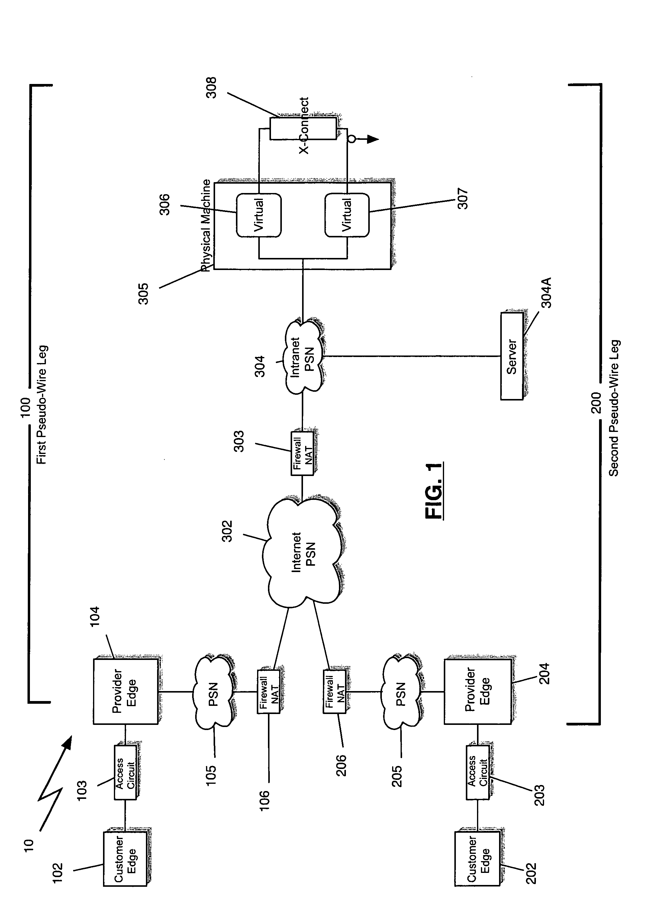
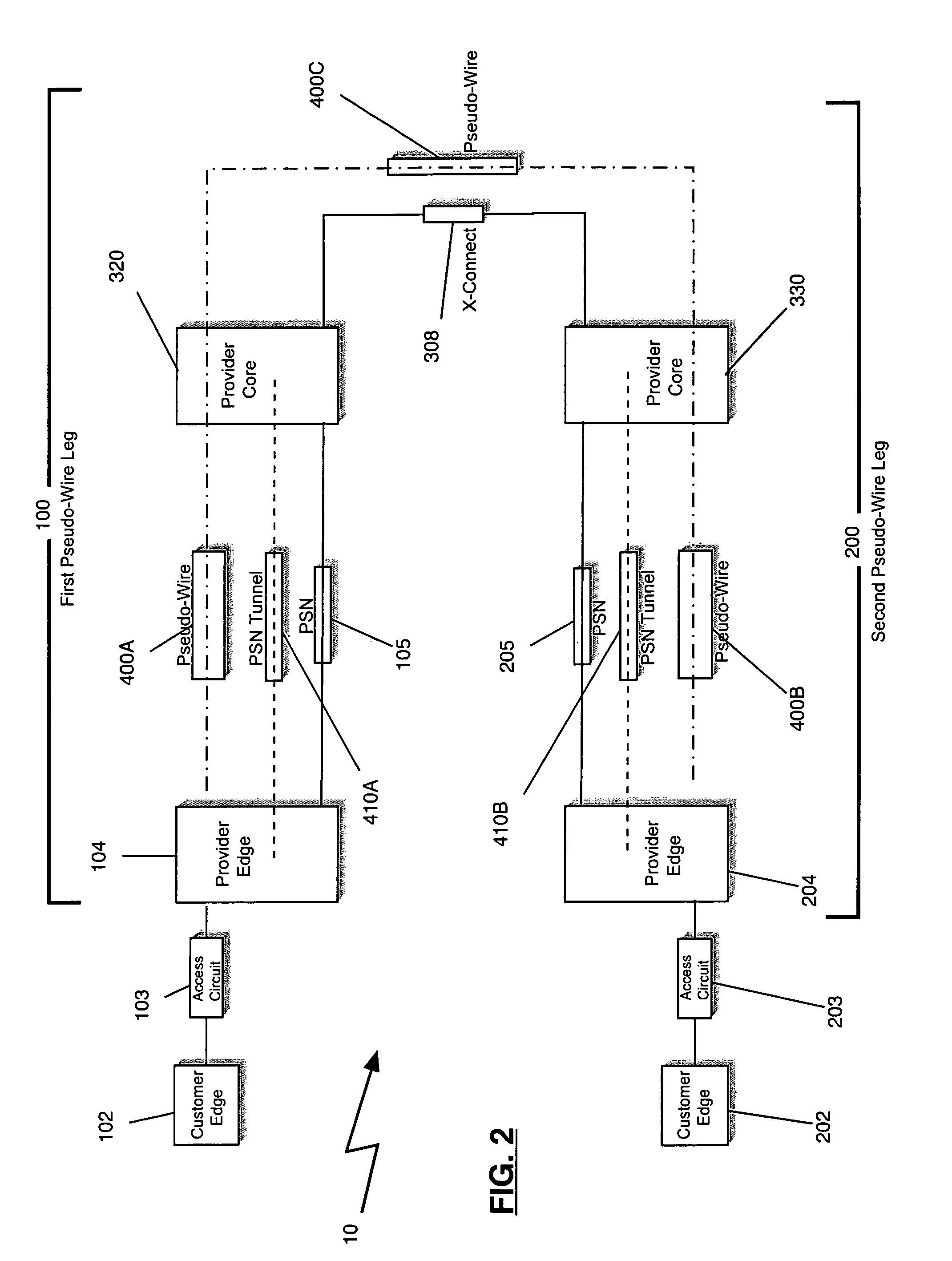
The patent is about a method and system for quickly setting up a layer-2 Pseudo-wire connection over unknown IP networks. It uses a Provider-Edge appliance at a customer site and a Provider-Core appliance at a hub / service site. The Provider-Edge appliance connects to the customer site through a trunk network, while the Provider-Core appliance connects to the Provider-Edge appliance using a pseudo- wire connection. This allows for the quick and efficient deployment of a layer-2 service over IP networks.

Problems solved by technology

When devices attempt to use a medium simultaneously, frame collisions occur.
There are OSI Physical Layer sniffers, which can capture and display the Preamble and Start Frame but they are expensive and mainly used to detect physical related problems.
That transfer can be reliable or unreliable.
Many data link protocols do not have acknowledgments of successful frame reception and acceptance, and some data link protocols might not even have any form of checksum to check for transmission errors.
The Network Layer performs network routing functions, and might also perform fragmentation and reassembly, and report delivery errors.
The direct peer-to-peer Pseudo-wire services are limited because they require special firewall configurations to permit them to work in most public Internet networks.
This is cumbersome for both the Telco and the customer and if a customer uses many Telcos such Layer-3 co-operation can become onerous and unworkable.
Still further, when a Telco provides a Layer-3 service to a customer, then the Telco has access to the customer's Layer-3 network, which is a potential security risk.
First, the Telco Layer-2 services can only be provisioned across the Telco's core network and other networks with Telco-Telco Network-Network Interconnect (NNI) agreements.
Second, the Telco usually takes 30-90 days to implement and integrate such additional Layer-2 services into existing Telco core network and other networks with Telco interconnect agreements.
These arrangements make it difficult to provide services to sites that are not served by the Telco's own or interconnected infrastructure and make it difficult to provide services rapidly.
Another important issue with Telco Layer-3 network offerings is mismatched features and requirements between or among networks.
Unless the carriers have the same number of classes of service, each with identical parameters, it is extremely difficult to translate services between carriers at the NNI in a way that meets the end customer's desired level of service from the carrier or carriers.
Other problems include mismatched inter-carrier logical and physical interfaces, transport methods, packet encapsulation, and the like.
Unless both carriers agree on the physical media and the have such physical media available, then such inter-carrier logical and physical interfaces are incompatible.
These are only a few of the many and sundry problems that are associated with providing Telco services, generally, and Telco Layer-2 services, specifically.
These are problems that have been present since the inception of providing Telco services.
Further, the many and sundry problems exist in an industry with stellar, first-rate technical capabilities and personnel.
Unfortunately, neither the stellar, first-rate technology nor the stellar, first-rate personnel have been able to solve the many problems associated with providing such services.
To the contrary, as the demand for additional Telco services has risen, the problems associated with providing the services has exceed the demand.
There exists no likelihood of success with respect to solving the type of persistent problems herein discussed, and to achieve success over such problems is unexpected.
The above features of the present disclosure are of high value to industry and the problems are not well addressed, if at all, by existing solutions and methods.

Method used


Image

  • Method and system for layer-2 pseudo-wire rapid-deployment service over unknown internet protocol networks
  • Method and system for layer-2 pseudo-wire rapid-deployment service over unknown internet protocol networks
  • Method and system for layer-2 pseudo-wire rapid-deployment service over unknown internet protocol networks

Examples


Embodiment Construction

[0052]Reference will now be made in detail to the present preferred embodiments of the invention as described in the accompanying drawings.

[0053]The method and system for the rapid-deployment and delivery of a Layer-2 Pseudo-wire across a set of unknown Internet Protocol networks and / or Packet Switched Networks including the public Internet is termed as FastL2 technology.

[0054]In order to understand the various aspect of the FastL2 technology, an understanding of the technology directly related to the present disclosure is provided. Generally, the FastL2 technology uses the fundamental technology building blocks that are available through IEEE standards (Ethernet, Posix, etc.), IETF standards (TCP / IP, VPNs, etc.), ISO standards (OSI, etc.), and FSF GPL licensed software (Linux Kernel, OpenVPN, Compression, Encryption, etc.).

[0055]Ethernet was initially developed by Xerox (Ethernet I) as disclosed in U.S. Pat. No. 4,063,220. Dec, Intel and Xerox collaborated on Ethernet II (aka DIX E...


PUM


Abstract

An International Standards Organization (“OSI”) Layer-2 (“Ethernet”) Pseudo-wire (“OSI Layer-1 type service”) appliance, method, system and hub service is disclosed. The method and system facilitate the rapid deployment of Layer-2 Pseudo-wires over unknown and untrusted Internet Protocol (“IP”) networks. The method and system facilitate the fluid edge of corporate networks and any situation where the Layer-3 network addresses cannot be changed.

Description

FIELD OF THE INVENTION[0001]The present disclosure relates to a method and system for digital telecommunications. More particularly, the disclosure relates to a method and system for the rapid-deployment and delivery of a Layer-2 Pseudo-wire across a set of unknown Internet Protocol networks and / or Packet Switched Networks including the public Internet.BACKGROUND OF THE INVENTION[0002]The Open Systems Interconnection model (OSI model) is a product of the Open Systems Interconnection effort at the International Organization for Standardization. It is a way of sub-dividing a communication system into smaller parts called layers. A layer is a collection of conceptually similar functions that provide services to the layer above it and receives services from the layer below it. On each layer an instance provides services to the instances at the layer above and requests service from the layer below.[0003]For example, a layer that provides error-free communications, across a network provid...

Claims


Application Information

Patent Timeline
Patent Type & Authority Patents(United States)
IPC IPC(8): G01R31/08
CPCH04L45/68H04L47/10H04L49/35
Inventor HINZ, MICHAELHINZ, WILLIAMSTEVENSON, DOUGLASEVERITT, TIMOTHY
Owner YR20 GROUP
Learn More