Multi-degree-of-freedom test stand for unmanned air vehicles

a technology of unmanned air vehicles and test stands, applied in the field of multi-degreeoffreedom (dof) gravity balanced uavs and/or mav test stands, can solve the problems of flying vehicles that can crash or fly out of control, ground-fixed test stands that add extra load to the test vehicle, and extra load may be too large to cope with extra load, so as to reduce the impact of uav during landing

Active Publication Date: 2013-01-15
ARROWHEAD CENT
View PDF30 Cites 68 Cited by
  • Summary
  • Abstract
  • Description
  • Claims
  • Application Information

AI Technical Summary

Benefits of technology

[0011]An embodiment of the present invention preferably comprises a stick disposed on an outer end of said arm, wherein said joint is disposed on said stick of said arm. This embodiment also optionally comprises a platform disposed between the stick and the joint and a damper disposed on a bottom portion of the stick for reducing impact on the UAV during landing. The spring preferably comprises a linear spring.
[0015]Another embodiment of the present invention comprises a method for testing an unmanned aerial vehicle (UAV). This method preferably comprises providing a stand comprising an arm having at least two members, the arm providing at least three degrees of freedom to the UAV, disposing a joint on the arm of the stand, the joint providing at least three degrees of freedom to the UVA, attaching the UAV to the joint, and testing the UAV. The method preferably includes gravity balancing the stand via at least one spring and reducing impact on the UAV during landing by providing a dampener. This method also preferably comprise flying the UAV and landing the UAV.

Problems solved by technology

It is a tremendous challenge to test autonomous flight capability of an UAV or MAV such as an autonomous helicopter.
This is because the flying vehicle can crash or fly out of control when the flight control system does not perform properly.
However, a ground-fixed test stand has the drawback of adding extra load to the test vehicle, which is inconsistent with a real flight case.
For small-scale UAVs, such as MAVs, this extra load may be too large to cope with.
Undoubtedly, active test stands are complicated in both design and operation.
They are also subject to reliability problems.
However, using counterweight adds additional weight to the system resulting in larger moments and products of inertia of the system.

Method used


Image

  • Multi-degree-of-freedom test stand for unmanned air vehicles
  • Multi-degree-of-freedom test stand for unmanned air vehicles
  • Multi-degree-of-freedom test stand for unmanned air vehicles

Examples


example 1

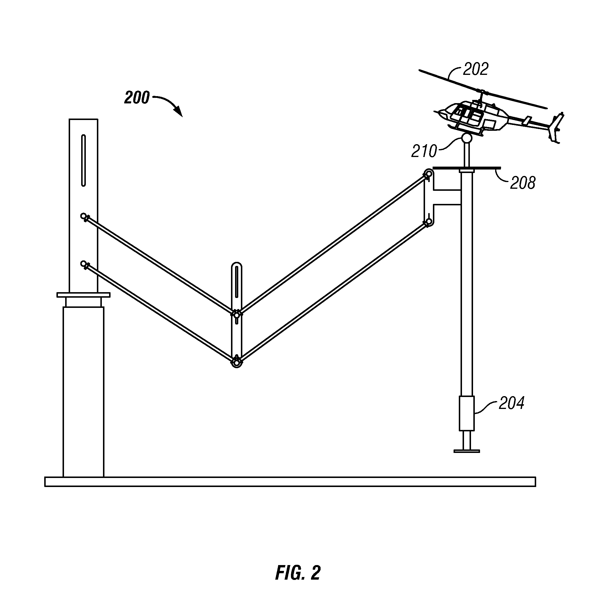
[0064]By applying the equations discussed above, one embodiment of a gravity balanced test stand was built. The following parameters of this embodiment were specified with respect to the working space requirements, i.e.

m1=m2=2.5 kg; m3=2 kg; m12=1.5 kg

l1=l2=0.5 m; r1=r2=0.25 m;

d1=d2=0.2 m; g=9.81 m / s2  (8)

[0065]Substituting these parameters into Eq. (6) leads to

k1=539.55 N / m; k2=171.68 N / m  (9)

[0066]With these spring stiffness values and the system parameters from the design, the gravity force of the system is balanced.

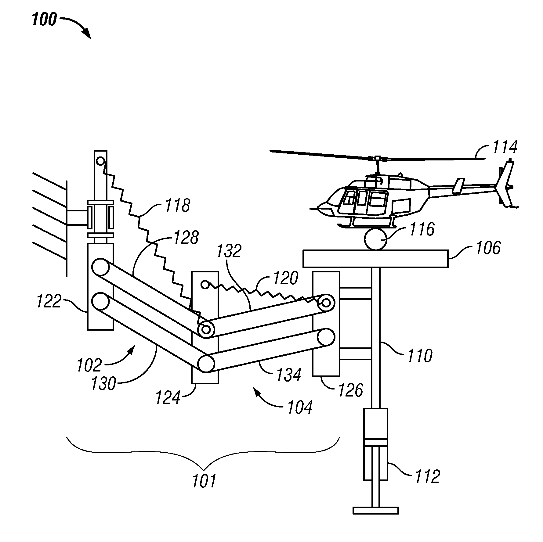
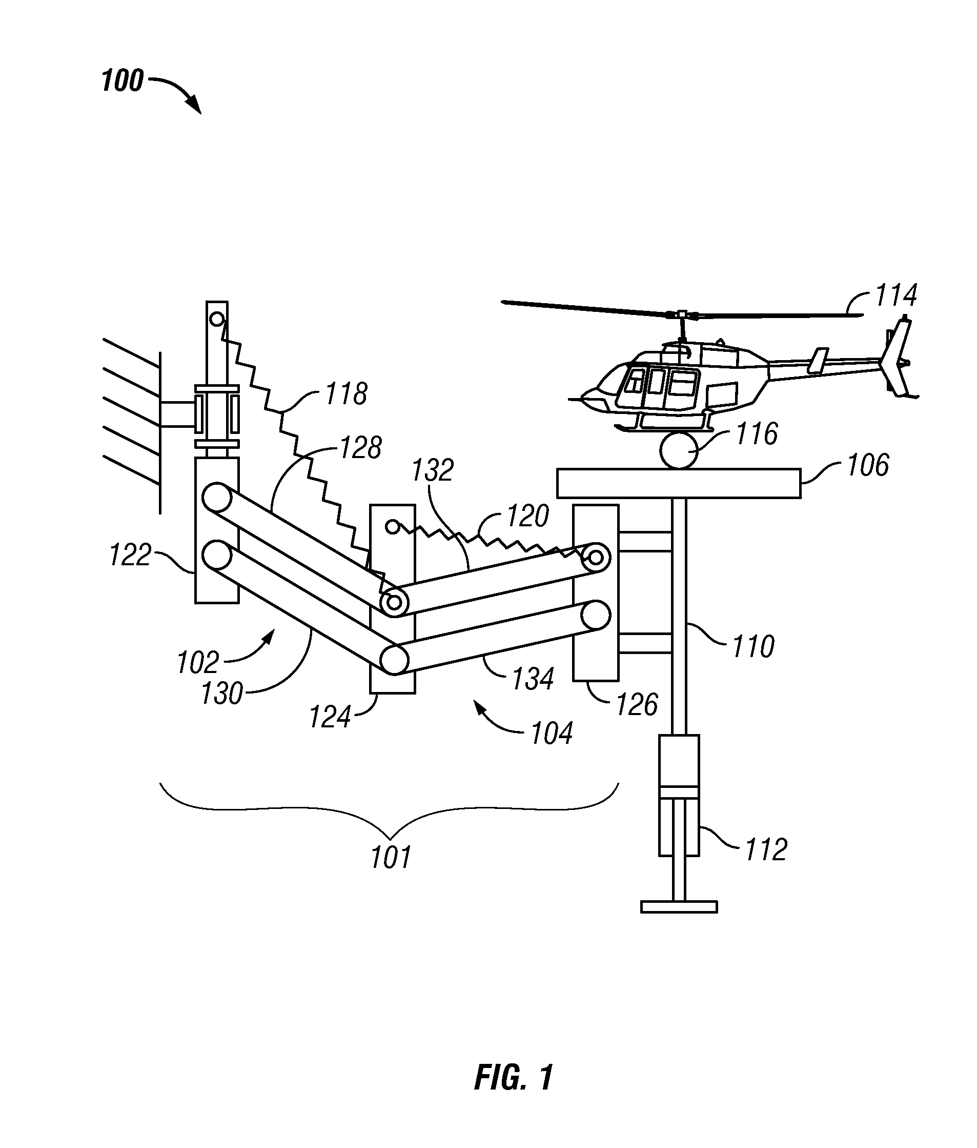
[0067]To compare the stand with and without gravity balancing, a dynamic simulation model of a test stand was created and is illustrated in FIG. 6. In this example, the parameters of stand 600 in this model are the same as those given above. The mass of UAV 602, which is a small helicopter in this example, is approximately mH=3 kg.

[0068]In this example, a concentrated lifting force was applied to UAV 602 at its center of mass (CM), such that UAV 602 hovered at initial...

example 2

[0070]In a second example, a sinusoidal disturbance was added to the lifting force along the Z direction (the vertical direction). The resulting external force is expressed as

FL=FZ+0.05mHg sin(10t)  (10a)

FA=FX  (10b)

where FZ and FX are the required lifting and axial forces. As a reference, the behavior of a UAV without the stand was also simulated. FIG. 9 is a graph which illustrates the vertical displacement of a UAV subject to disturbance under these three conditions.

[0071]As illustrated in FIG. 9, due to the sinusoidal disturbance, the UAV no longer hovers at the initial position. Instead, a stand without gravity balancing constrains the motion of a UAV and leads to an oscillation around the initial position. The gravity balanced stand allows the UAV to drift up continuously, which is closer to the real behavior of a free flying UAV. Because of the dynamic loading (i.e. the inertia force) applied to the UAV by the stand, the UAV with a gravity balanced stand drifts less than the ...

example 3

[0072]The force in a joint between a UAV and a stand was also measured to illustrate the effect on the UAV that is added by the stand, as illustrated in FIGS. 10 and 11.

[0073]Both the vertical (Z) and the horizontal (X) joint force of the gravity balanced system remains close to zero, except for a slight vibration due to the added periodical disturbance. However, the forces of the non-gravity balanced system are not close to zero and vary with the initial position. The results seen in FIGS. 10 and 11 show that a test stand with gravity balancing places much less burden on a tested vehicle, which allows the vehicle to be tested under a condition much closer to reality.

[0074]The gravity balancing technology as described in the embodiments of the present invention results in a test stand that compensates its own weight for all working configurations. Thus, the gravity force of the stand does not add any load to the vehicle being tested with the stand. Gravity balancing is preferably ac...


PUM


Abstract

The invention is a multiple degree-of-freedom test stand for unmanned air vehicles, and is particularly useful for small or micro unmanned air vehicles. The stand is gravity balanced using springs such that no weight of any part of the stand becomes a burden to the tested vehicle when it flies while constrained to the stand. A joint and a plurality of members are used to enable multiple degrees of freedom.

Description

CROSS-REFERENCE TO RELATED APPLICATIONS[0001]This application claims priority to and the benefit of the filing of U.S. Provisional Patent Application Ser. No. 61 / 170,445, entitled “Multi-Degree of Freedom Test Stand for Unmanned Air Vehicles”, filed on Apr. 17, 2009, and the specification thereof is incorporated herein by reference.STATEMENT REGARDING FEDERALLY SPONSORED RESEARCH OR DEVELOPMENT[0002]The U.S. Government has sponsored in-part research for this invention, which gives the government certain rights to the invention as provided for by the terms of Contract No. FA9200-06-D-0020 awarded by the U.S. Air Force.BACKGROUND OF THE INVENTION[0003]1. Field of the Invention (Technical Field)[0004]The present invention relates to a test stand for unmanned air vehicles (UAVs) and / or micro air vehicles (MAVs) and more particularly to a multi-degree-of-freedom (DOF) gravity balanced UAV and / or MAV test stand.[0005]2. Description of Related Art[0006]It is a tremendous challenge to test ...

Claims


Application Information

Patent Timeline
Patent Type & Authority Patents(United States)
IPC IPC(8): B64C17/00F16M11/00A63H27/00A47B9/02
CPCB64F5/0045A63H27/12F16M11/14F16M11/2092F16M11/24F16M2200/044F16M2200/063B64F5/60
Inventor MA, OUORTEGA, CARLOS E.RUBLE, KENLU, QI
Owner ARROWHEAD CENT
Why Eureka
Try Eureka