Sperm collection device

a collection device and sperm technology, applied in the field of sperm collection devices, can solve the problems of disadvantages in cost performance, environmental load, and difficulty in taking out only the interior members of the collection device, and achieve the effects of simple structure, improved workability, and improved feeling of us

Active Publication Date: 2013-01-15
TENGA
View PDF31 Cites 17 Cited by
  • Summary
  • Abstract
  • Description
  • Claims
  • Application Information

AI Technical Summary

Benefits of technology

[0016]Since the two core pieces constitute a bag-like core member when they are closed and insertion empty space is opened when the core pieces are opened, the core pieces can be easily rinsed. Further, since the core pieces can be easily manufactured by injection molding, an arbitrary layout can be employed as a shape of an inner surface of the insertion empty space.
[0030]Besides for medical purposes, the sperm collection device in accordance with one or more embodiments of the present invention can be used as a means for satisfying important social requirements, such as improving the quality of life (QOL) for elderly men and disabled persons.

Problems solved by technology

However, since this type of the sperm collection device has such a structure that the bag-like interior member is fixed in the vessel main body, it is difficult to take out only the interior member.
Accordingly, the sperm collection device is not suitable to repeatedly use the interior member without a hygienic problem by rinsing the inside thereof and thus basically a disposable type.
As a result, the sperm collection device is disadvantageous in a cost performance and a load on an environment.
Even if the concave space in the interior member stored in the vessel main body is forcibly rinsed, since it is difficult to entirely rinse it, a repeated use thereof is unhygienic.
Thus, it is difficult to adjust a degree of pressure applied to the penis and a portion to which pressure is applied by band.
Further, when the interior member having the bag-like arrangement is manufactured by injection molding, it is difficult to form a complex shape (a projection, a fold, and the like) to the inside of the interior member when it is taken into consideration to remove the interior member from a mold, and the like.
However, even these sperm collection devices have the same problem as that of Patent Document 1.Patent Document 1: Japanese Utility Model Registration No. 3076627Patent Document 2: Japanese Patent Application Laid-Open No. 2006-334176Patent Document 3: Japanese Patent Application Laid-Open No. 2006-340870Patent Document 4: Japanese Patent Application Laid-Open No. 2006-340871

Method used


Image

  • Sperm collection device
  • Sperm collection device
  • Sperm collection device

Examples


Embodiment Construction

[0041]The present invention will be described below in detail by an embodiment shown in drawings. Numerous specific details are set forth in order to provide a more thorough understanding of the invention. However, it will be apparent to one of ordinary skill in the art that the invention may be practiced without these specific details. In other instances, well-known features have not been described in detail to avoid obscuring the invention.

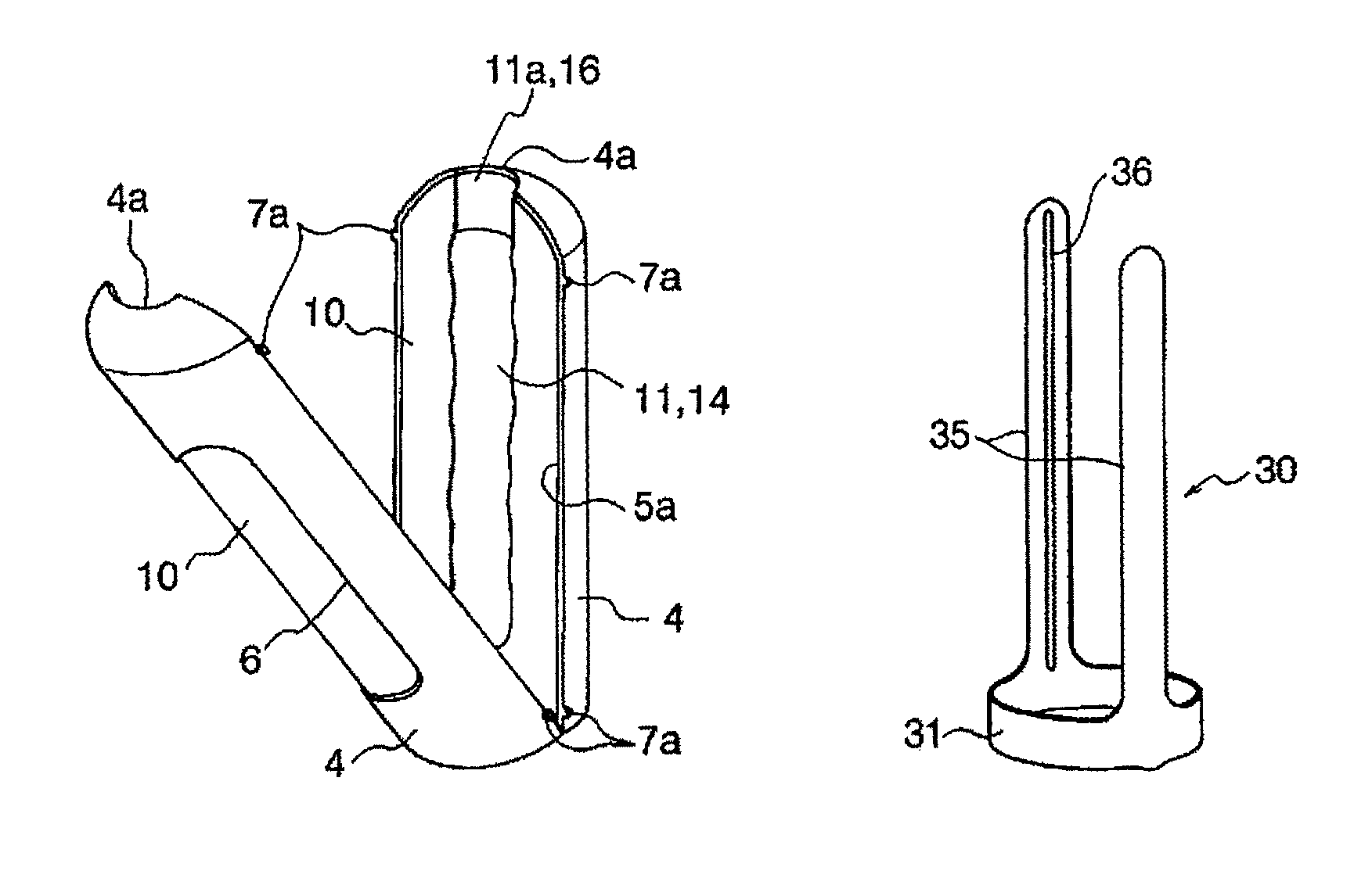
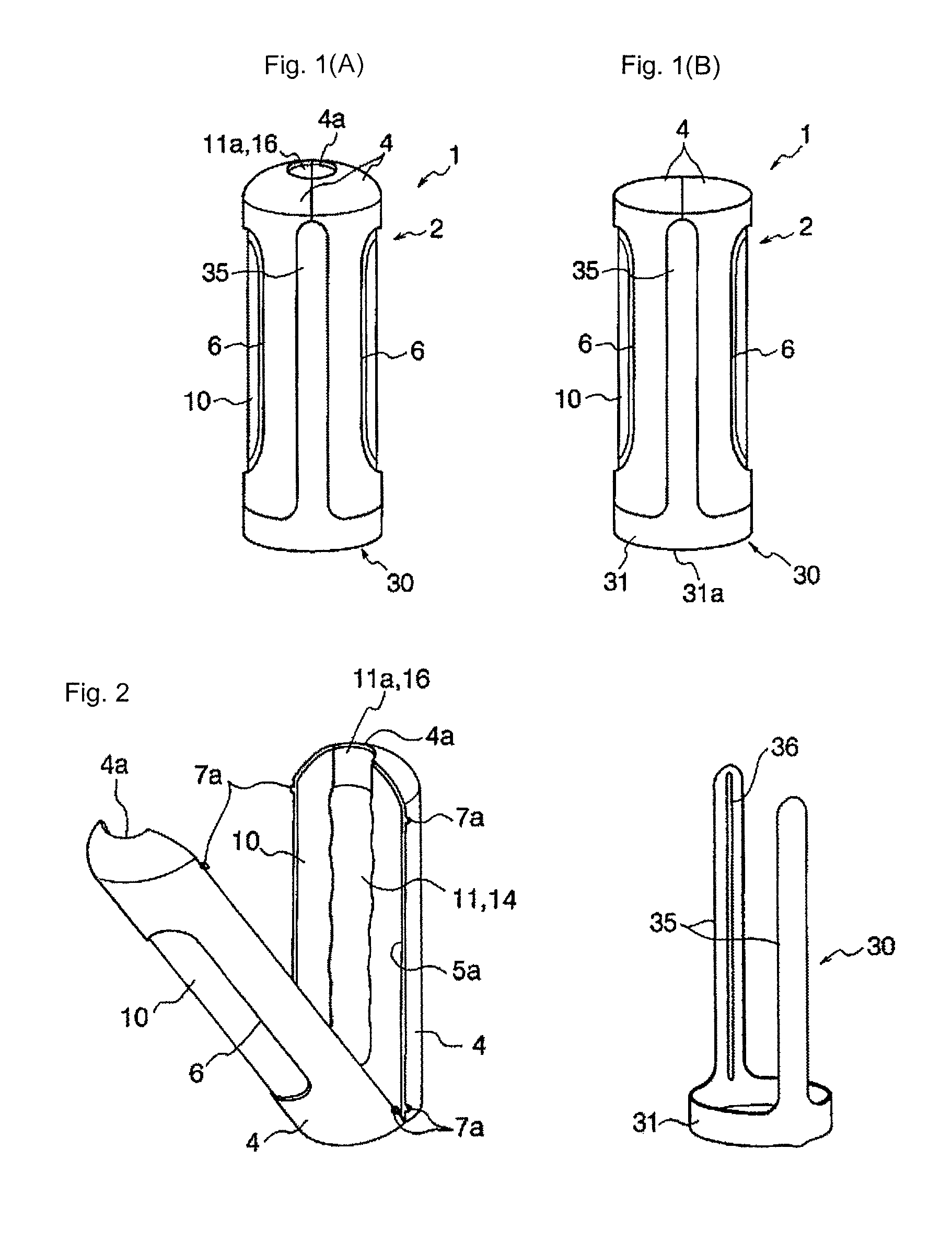
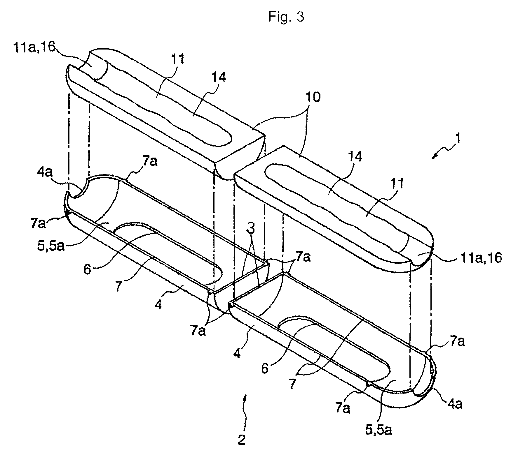
[0042]FIGS. 1(a) and (b) are perspective views showing an assembled state of a sperm collection device according to an embodiment of the present invention, FIG. 2 is a perspective view showing a state that an open / close unit and a holder, which constitute the sperm collection device, are separated from each other, and FIG. 3 is an exploded perspective view showing an arrangement the open / close unit.

[0043]The sperm collection device 1 is composed of the open / close unit 2 and the holder 30. The open / close unit 2 is composed of two open / close membe...


PUM


Abstract

A sperm collection device includes an open / close unit including two open / close members openably and closably supported about a hinge and core pieces supported by the open / close members. The core pieces are configured to open and close with the open / close members and to form an insertion space when the open / close members are closed.

Description

TECHNICAL FIELD[0001]The present invention relates to a sperm collection device, and more particularly to an improvement of a sperm collection device which has been conventionally used based on requirements for a medical research and a treatment and on a social requirement for prevention of a sex crime, prostitution, and spreading of sexually-transmitted disease, and the like.BACKGROUND ART[0002]There are proposed various sperm collection devices for obtaining men's sperm from a necessity of a medical research and a treatment. The sperm collection devices are used for a medical necessity, for example, examining a husband's sexual function from sperm collected to investigate a cause of conjugal infertility, treating sexual dysfunction, and securing sperm for artificial insemination. There is conventionally known a simple sperm collection device which can be obtained at a low cost and does not cause a hygienic and health problems because it is a disposable type to satisfy various soci...

Claims


Application Information

Patent Timeline
Patent Type & Authority Patents(United States)
IPC IPC(8): A61F5/44
CPCA61B10/0058
Inventor MATSUURA, TSUTOMU
Owner TENGA
Why Eureka
Try Eureka