Systems and methods for raster-to-block converter

a technology of raster-to-block converter and system method, applied in the field of digital image processing, can solve the problems of complex and not easily scalable, video memory is usually very high performance and expensive, and the cost of memory is usually twice the cost, and achieves the effect of sufficient capacity

Active Publication Date: 2013-01-15
SYNAPTICS INC
View PDF13 Cites 74 Cited by
  • Summary
  • Abstract
  • Description
  • Claims
  • Application Information

AI Technical Summary

Problems solved by technology

A difficulty arises because image sources and image displays tend to operate in raster order and image compression systems operate in block order.
However, the difficulty arises when as the first image band is read from the buffer, a second image band is written in. FIG. 4A shows the image band buffer with the first block vacated.
While this architecture converts from raster order to pixel order effectively, it does at the expense of twice the memory cost.
While in today's age of copious memory, this may not seem like a lot, video memory is usually very high performance and expensive, especially when incorporated into an integrated circuit.
The aforementioned U.S. Pat. No. 5,446,560, does provide a system for conversion between raster and block ordering that requires only one image band buffer, but it is complicated and not easily scalable.

Method used


Image

  • Systems and methods for raster-to-block converter
  • Systems and methods for raster-to-block converter
  • Systems and methods for raster-to-block converter

Examples


Embodiment Construction

[0053]A detailed description of embodiments of the present invention is presented below. While the disclosure will be described in connection with these drawings, there is no intent to limit it to the embodiment or embodiments disclosed herein. On the contrary, the intent is to cover all alternatives, modifications and equivalents included within the spirit and scope of the disclosure.

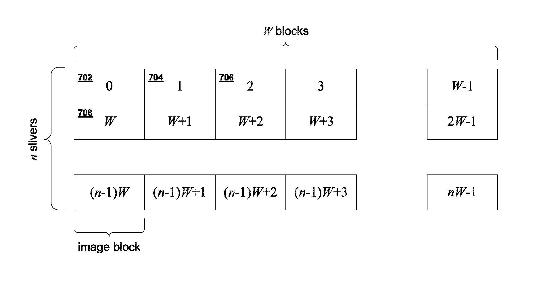
[0054]Rather than ping-ponging between two image band buffers, an incoming pixel can be stored in a memory location vacated by an outgoing pixel. By doing this, the order in which the addresses should be read ultimately will be scrambled. However, each row of any given block will remain continuous. Therefore, it is convenient to refer to a row of a block as a sliver. Therefore, an m×n block will comprise n m×1 slivers. For the foregoing discussion, it is convenient to describe a general image raster to block converter in terms of the following parameters. A block is denoted as having m×n pixels. The im...


PUM


Abstract

A raster to block converter and equivalently a block to raster converter can be implemented using enough memory to contain a single image band, that is a band of pixels of height equal to a single block but spanning the entire width of an image. The raster to block converter can operate at full rate so that as soon as a pixel is read out from the memory a new pixel can be stored in its place. The location of a pixel can be tracked using a mapping involving basic modular arithmetic. This raster to block converter is scalable so that it can work with any size image and block size.

Description

BACKGROUND OF THE INVENTION[0001]1. Field of the Invention[0002]The present invention relates to the processing of digital images and more specifically to the conversion between images transported in raster order to images transported in block order.[0003]2. Related Art[0004]In modern electronics, a digital image comprises a set of pixels. Each pixel has associated with it a pixel value and pixels are usually laid out in a two-dimensional grid covering the image. The pixel value can be a single numeric value or a set of numeric values. For example, in a monochromatic image, a pixel value is typically a single number representing the intensity or luminance. For polychromatic or color images, the pixel value can be one of several schemes based on the type of color space used. It can be represented by a number for luminance (Y) and two numbers for chrominance (Cr, Cb). It can also be red-green-blue (RGB) or cyan-yellow-magenta-black (CYMK) color spaces. The space of one of these colors...

Claims


Application Information

Patent Timeline
Patent Type & Authority Patents(United States)
IPC IPC(8): G06K9/00
CPCH04N19/61H04N19/85H04N19/42
Inventor KARSANBHAI, MANHARBROOKS, JOHN M
Owner SYNAPTICS INC
Why Eureka
Try Eureka