Durable target apparatus and method of on-target visual display

a visual display and target technology, applied in the field of targets, can solve the problems of time-consuming and labor-intensive approach to determining the shot location, the inability of shooters to see the point of impact of the bullet on a typical non-durable paper target downrange, and the difficulty of improving shooter proficiency. achieve the effect of improving shooter proficiency

Active Publication Date: 2013-01-22
REAL TIME TARGETAB
View PDF20 Cites 32 Cited by
  • Summary
  • Abstract
  • Description
  • Claims
  • Application Information

AI Technical Summary

Benefits of technology

[0010]One or more embodiments of the invention enable a durable target apparatus and method of on-target visual display. In various embodiments of the invention, pie-shaped target sectors surround a bull's eye sector. However, target sectors, if seen on the face of the target at all, may form a circle, octagon, square, rectangle or any other geometric shape. Each sector may be associated with one or more illuminated display segments. The display segments are visible at a distance, enabling shooters to determine the sector hit, and to adjust a next shot without looking away from the target, thereby improving shooter proficiency. Various training mode are available. Methods for determining the target sector impacted and algorithms for asserting the correct display segment(s) are described. By utilizing on-target display segments, embodiments of the invention enable a shooter to ascertain the accuracy of the shot without looking away from the sights on the firearm or from the target.
[0011]The target apparatus of the invention is configured to be durable. In a preferred embodiment, the target apparatus is impenetrable to bullets of any caliber by providing a target plate thick and strong enough to deny passage of a bullet through the apparatus. Thus, the apparatus does not have to be replaced as paper targets do, therein lowering long term shooting costs. A target surface durable enough to withstand repeated shot impacts, for example a surface with a Brinell hardness of about 400 or higher, may also be supported with a dampening material, such as polyurethane or Styrofoam, coupled to the reverse side of the target surface to slow down the impact shock wave and allow iterative scanning by sensors designed to locate the impact of the shot on the target.
[0012]One or more embodiments of the invention provide on-target display segments to enable shooters to determine the approximate location of a hit on the target quickly. While display segments are described herein as “display lights,” one or more embodiments may use alternative methods of indicating the target sector that was hit by the shot. For example, the color of the target sector itself might be changed. Any other method of indicating the impacted sector known in the art and visible downrange by the shooter is within the scope of the invention. In preferred embodiments, the display segments are display lights that are within the shooter's field of view as the shooter aims at the target, therein providing immediate feedback as to the accuracy of the shot. In one or more embodiments of the invention, several pie-shaped wedges or target sectors surround a “bull's eye” at the center of the target. Display segments may be located on or near the target sectors, and in some embodiments may be located in or near the bull's eye itself, placing the feedback clearly within the shooter's field of view and clearly visible from an appropriate distance. In addition, use of on-target display segments enables embodiments of the invention to indicate the approximate location of the hit on the target without requiring the shooter to look away from the sights of the firearm or away from the target itself, allowing the shooter to set up the next shot without changing stance, which may be an improvement over some prior targets. This is particularly helpful for training when shooting targets at long distances where one cannot see an impact location of the bullet, for example on a conventional paper target.

Problems solved by technology

Traditionally, shooters who participate in target practice are unable to see the point of impact of the bullet on a typical non-durable paper target downrange because of the small diameter of the bullet hole on the target.
Not only is this approach to determining shot location time consuming, shooters have difficulty improving because they do not receive immediate feedback for every shot and in many cases are unsure as to which shot has produced which hole.
These targets still are problematic in that a shot through an existing hole in a target with two or more shots through it already provides no feedback to the user as to which hole the shot passed through.
In addition, these targets are non-durable, for example penetrable, so must be purchased and replaced, cannot be printed out directly by a shooter on his or her own printer, and must be patched to cover the holes with the same type of material that splatters or flakes.
It is impossible to put the firearm down and check each shot displayed on the monitor as each shot occurs in the time limit allotted.
For these systems, if a shot is directly in between two sensors, two lights may be presented causing confusion.
Hence, these systems are not suitable for “action” shooting, moving target practice, timed or rapid fire shooting.
Other systems drill holes in the back of the target which increases costs and in mentioned.

Method used


Image

  • Durable target apparatus and method of on-target visual display
  • Durable target apparatus and method of on-target visual display
  • Durable target apparatus and method of on-target visual display

Examples


Embodiment Construction

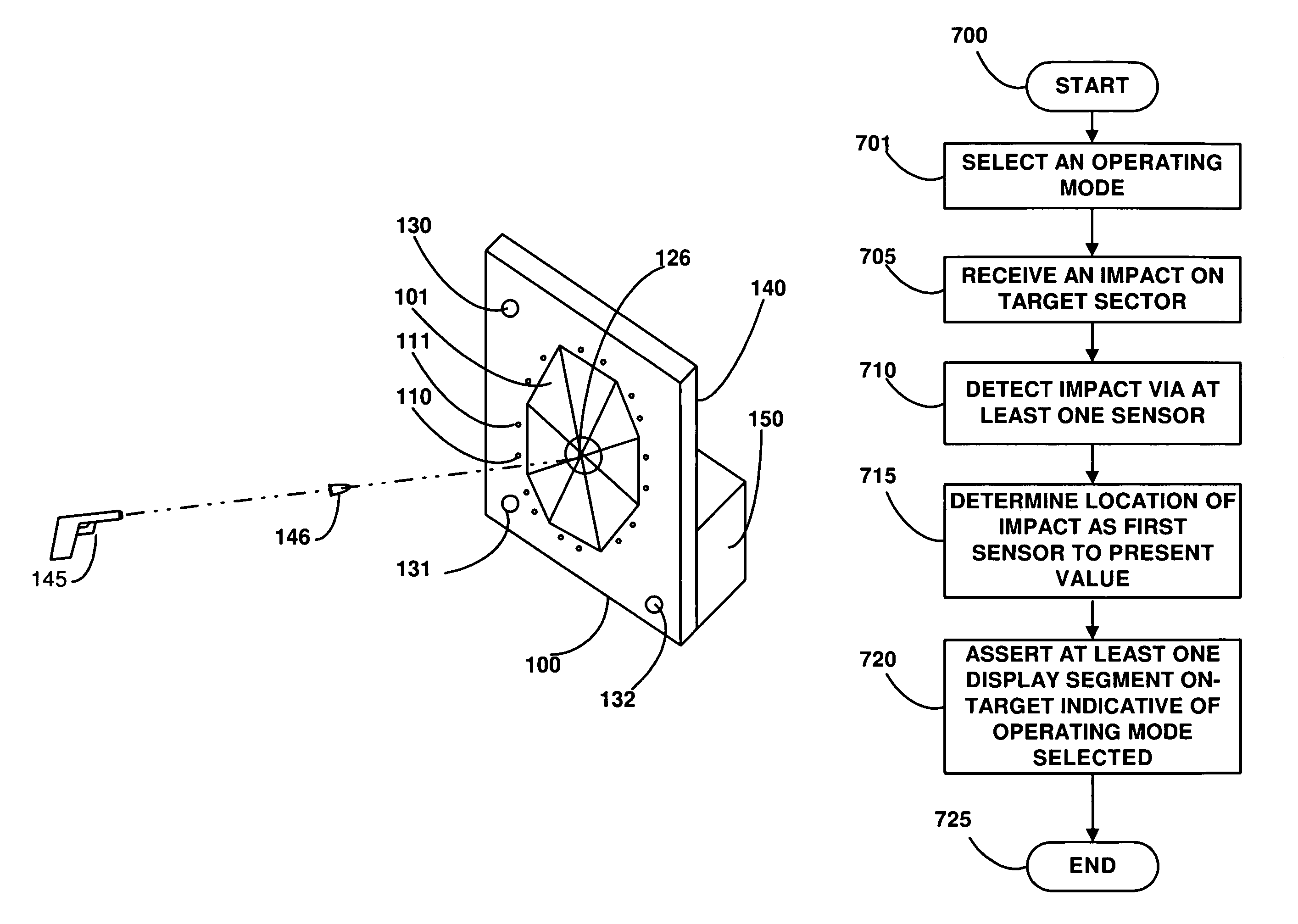
[0034]A durable target apparatus and method of on-target visual display will now be described. In the following exemplary description, numerous specific details are set forth in order to provide a more thorough understanding of embodiments of the invention. It will be apparent, however, to an artisan of ordinary skill that the present invention may be practiced without incorporating all aspects of the specific details described herein. In other instances, specific features, quantities, or measurements well known to those of ordinary skill in the art have not been described in detail so as not to obscure the invention. Readers should note that although examples of the invention are set forth herein, the claims, and the full scope of any equivalents, are what define the metes and bounds of the invention.

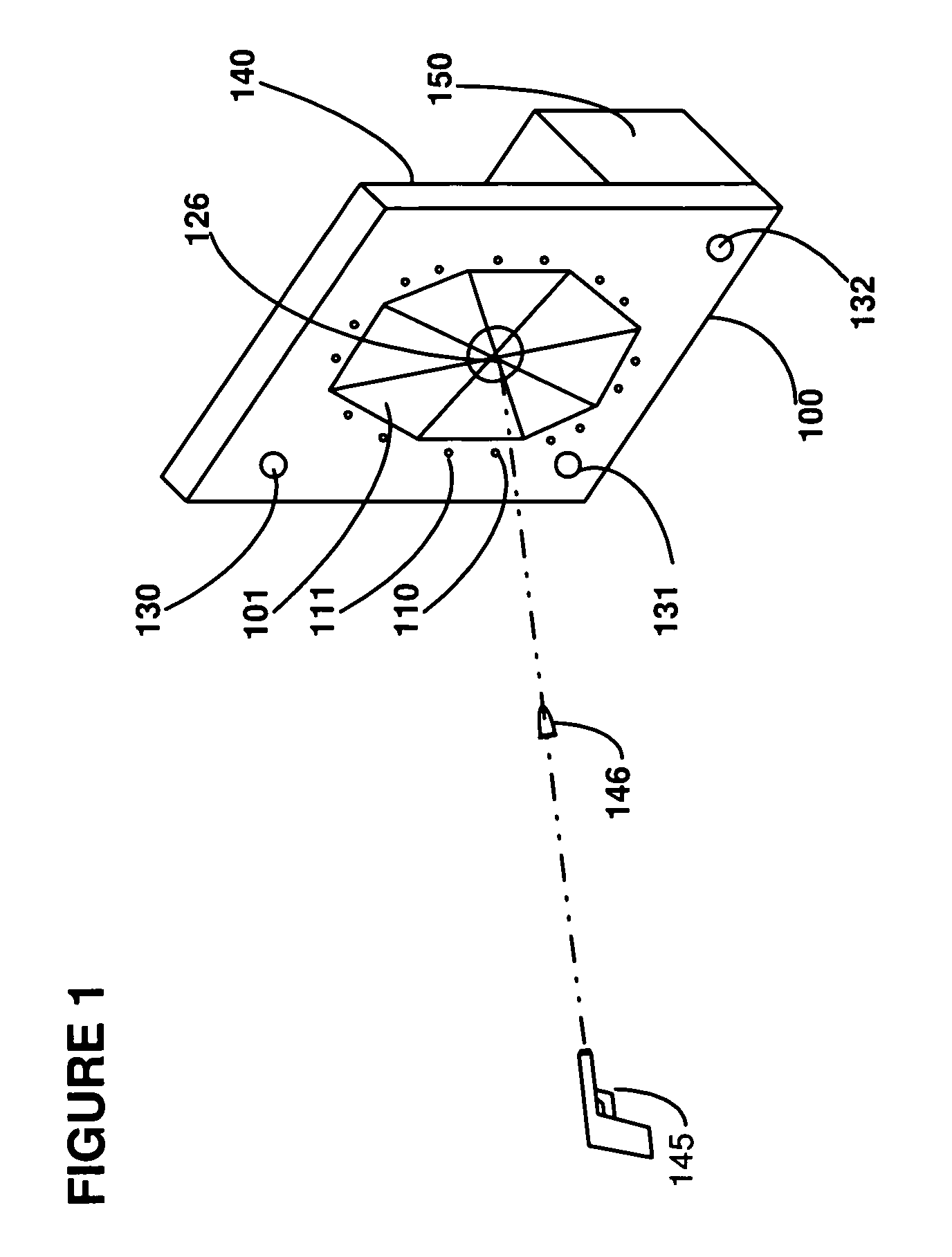
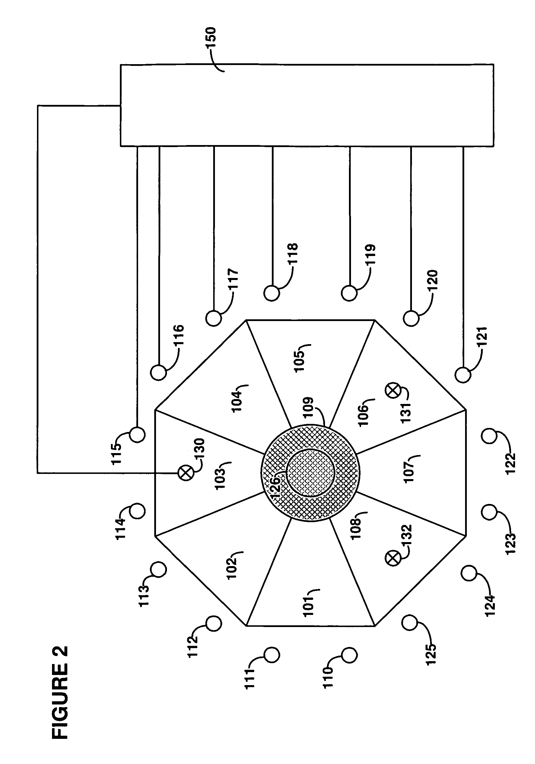
[0035]The invention comprises a target apparatus for firearms that is durable, portable, and easy to use. Though target apparatus 100 may be permanently installed in an indoor or outdo...


PUM


Abstract

A durable reusable target apparatus with on-target visual display is described. In embodiments of the invention, pie-shaped target sectors surround a bull's eye sector. Each sector may be associated with one or more illuminated display segments. The display segments are visible at a distance, enabling shooters to determine the sector hit, and to adjust a next shot without looking away, thereby improving shooter proficiency. Various training mode are available. Methods for determining the target sector impacted and algorithms for asserting the correct display segment(s) are described. By utilizing on-target display segments, embodiments of the invention enable the shooter to ascertain the accuracy of the shot without looking away from the sights on the firearm or from the target.

Description

BACKGROUND OF THE INVENTION[0001]1. Field of the Invention[0002]Embodiments of the invention described herein pertain to the field of targets. More particularly, but not by way of limitation, one or more embodiments of the invention enable a durable target apparatus and method of on-target visual display in which a shooter is presented with an on-target representation of the approximate location of a point of impact of a bullet fired by the shooter. In one or more embodiments of the invention, the shooter receives immediate visual feedback for each shot without requiring the shooter to look away from the target.[0003]2. Description of the Related Art[0004]Traditionally, shooters who participate in target practice are unable to see the point of impact of the bullet on a typical non-durable paper target downrange because of the small diameter of the bullet hole on the target. At a typical target practice session, shooters take one or more shots at a target, and then periodically set d...

Claims


Application Information

Patent Timeline
Patent Type & Authority Patents(United States)
IPC IPC(8): F41J5/04F41J5/14
CPCF41J5/041F41J5/056
Inventor MRAZ, ROCKY
Owner REAL TIME TARGETAB
Why Eureka
Try Eureka