
Large diopter range real time sequential wavefront sensor

a wavefront sensor and diopter range technology, applied in the field of ophthalmic wavefront sensors, can solve the problems of ophthalmic applications that require a large amount of optical power, the integration of the original ophthalmic instrument with the wavefront sensor is generally not aimed at maintaining the original ophthalmic instrument intact, and the bulky bulky wavefront sensor is generally bulky. , to achieve the effect of increasing the signal to noise ratio, increasing the optical power, and more consistent measurement of the wavefron

Inactive Publication Date: 2013-01-22
CLARITY MEDICAL SYST
View PDF23 Cites 33 Cited by
  • Summary
  • Abstract
  • Description
  • Claims
  • Application Information

AI Technical Summary

Benefits of technology

The present invention aims to make the surgical or eye examination working distance consistent for each clinician or surgeon while ensuring the optical energy collected from a patient eye is fully collected and the signal to noise ratio is maintained across the whole desired eye diopter range. Additionally, this invention uses CCD / CMOS image and pattern recognition combined with wavefront signal detection to smartly turn the SLD on and off to save exposure time and increase the signal to noise ratio.

Problems solved by technology

Wavefront sensors for ophthalmic applications are generally bulky and stand-alone desktop instruments.
Although there have been attempts to integrate a wavefront sensor with an ophthalmic instrument such as a LASIK system (see for example, U.S. Pat. No. 6,685,319), a fundus camera (see for example, U.S. Pat. No. 6,572,230), and a confocal scanning laser ophthalmoscope (see for example, U.S. Pat. No. 7,057,806), these integrations are generally not aimed at maintaining the original ophthalmic instrument intact with the wavefront sensor as a separate compact module attached to or integrated with the ophthalmic instrument.

Method used


Image

  • Large diopter range real time sequential wavefront sensor
  • Large diopter range real time sequential wavefront sensor
  • Large diopter range real time sequential wavefront sensor

Examples


Embodiment Construction

[0044]Reference will now be made in detail to various embodiments of the invention. Examples of these embodiments are illustrated in the accompanying drawings. While the invention will be described in conjunction with these embodiments, it will be understood that it is not intended to limit the invention to any embodiment. On the contrary, it is intended to cover alternatives, modifications, and equivalents as may be included within the spirit and scope of the invention as defined by the appended claims. In the following description, numerous specific details are set forth in order to provide a thorough understanding of the various embodiments. However, the present invention may be practiced without some or all of these specific details. In other instances, well known process operations have not been described in detail in order not to unnecessarily obscure the present invention. Further, each appearance of the phrase an “example embodiment” at various places in the specification do...


PUM


Abstract

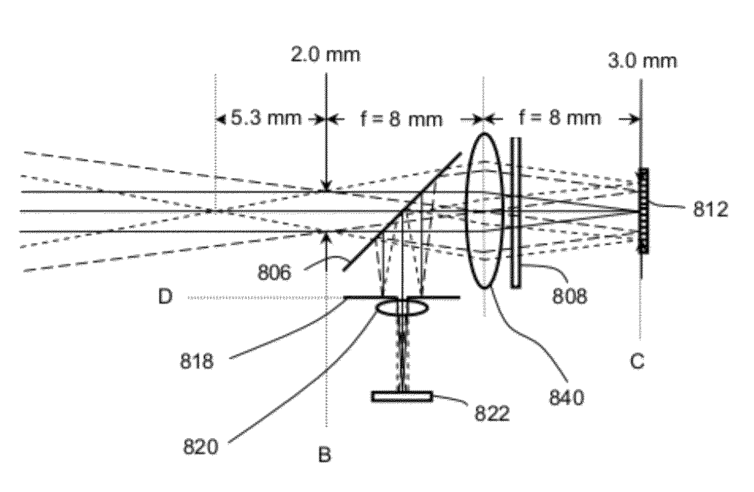
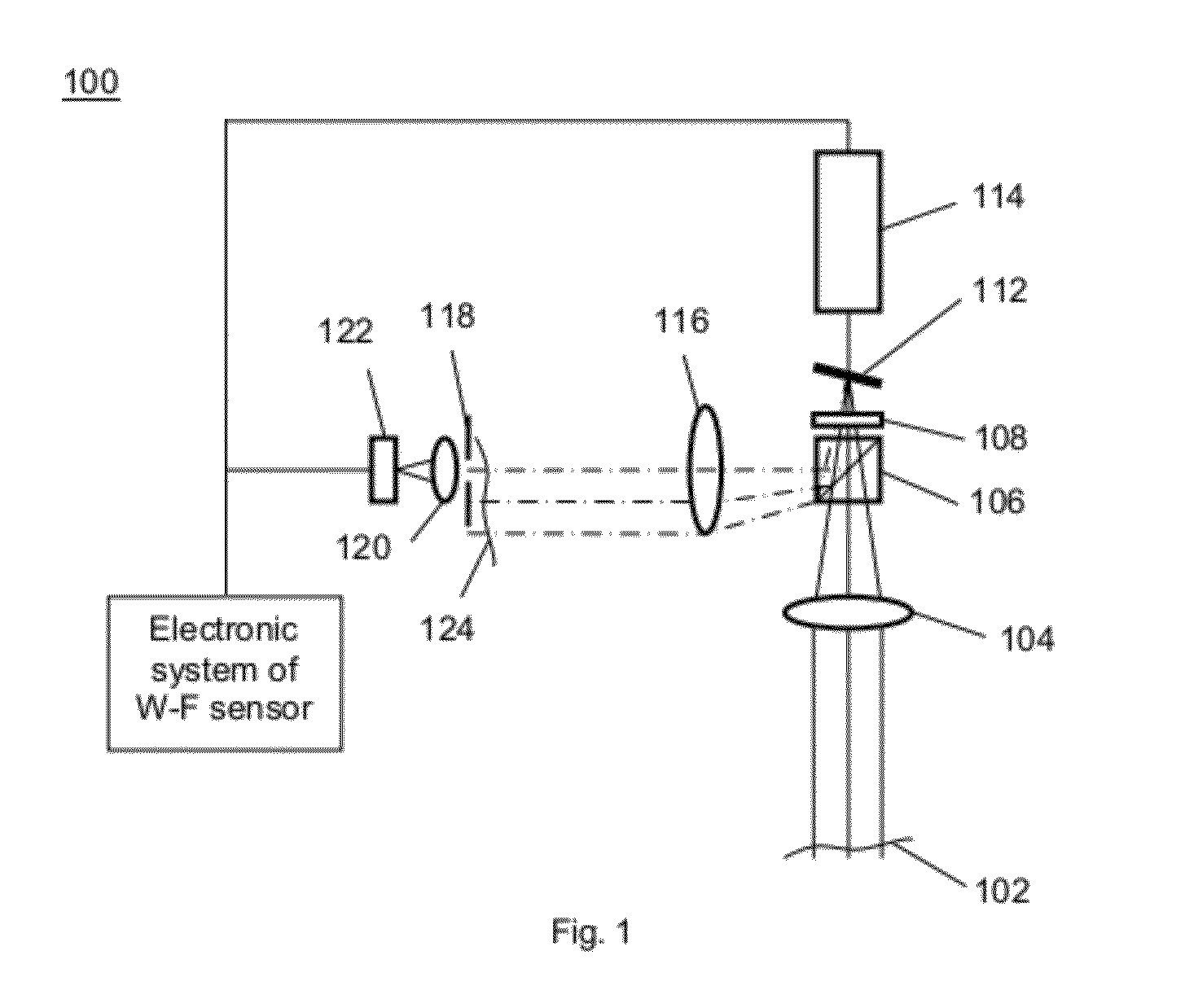
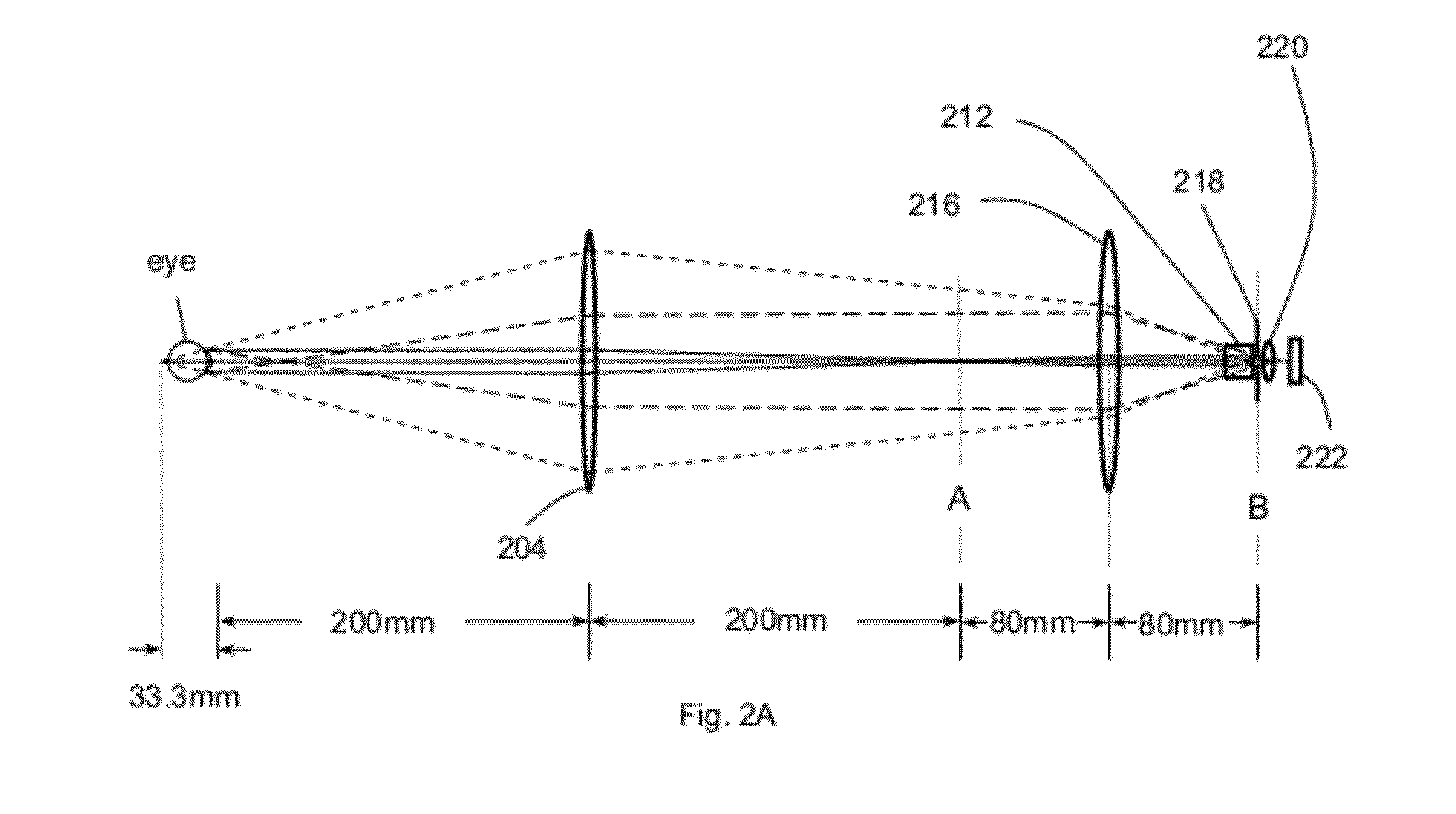
Example embodiments of a large dynamic range sequential wavefront sensor for vision correction or assessment procedures are disclosed. An example embodiment optically relays a wavefront from an eye pupil or corneal plane to a wavefront sampling plane in such a manner that somewhere in the relaying process, the wavefront beam from the eye within a large eye diopter range is made to reside within a desired physical dimension over a certain axial distance range in a wavefront image space and / or a Fourier transform space. As a result, a wavefront beam shifting device can be disposed there to fully intercept and hence shift the whole beam to transversely shift the relayed wavefront.

Description

RELATED APPLICATIONS[0001]This application is a continuation-in-part application of application Ser. No. 12 / 790,301 entitled Adaptive Sequential Wavefront Sensor with Programmed Control, filed May 28, 2010, which is a division of application Ser. No. 11 / 761,890 entitled Adaptive Sequential Wavefront Sensor and its Applications, filed Jun. 12, 2007, now U.S. Pat. No. 7,815,310 issued Oct. 19, 2010 which is a continuation-in-part of application Ser. No. 11 / 335,980 entitled Sequential Wavefront Sensor, filed Jan. 20, 2006, now U.S. Pat. No. 7,445,335 issued Nov. 4, 2008, all of which are incorporated by reference for all purposes.TECHNICAL FIELD OF THE INVENTION[0002]One or more embodiments of the present invention relate generally to ophthalmic wavefront sensors and particularly relate to wavefront sensor modules and their attachment to or integration with an ophthalmic instrument for vision correction surgical procedures and to integration with ophthalmic instruments for vision asses...

Claims


Application Information

Patent Timeline
Patent Type & Authority Patents(United States)
IPC IPC(8): A61B3/10
CPCA61B3/1015A61B3/12G01J9/00A61B3/1005G01J2003/064A61B3/102A61B3/103A61B3/107A61B3/117G02B13/0095G02B17/0896
Inventor ZHOU, YANSHEA, WILLIAM
Owner CLARITY MEDICAL SYST
Learn More