Method and system for optoelectronic receivers for uncoded data

a receiver and optoelectronic technology, applied in the field ofsignal processing, can solve the problems of cable bulk penalties, large power requirements, complex system, etc., and achieve the effects of simple system design, small improvement in reach and limited scalability, and complicated oe recovery

Active Publication Date: 2013-01-22
CISCO TECH INC
View PDF2 Cites 18 Cited by
  • Summary
  • Abstract
  • Description
  • Claims
  • Application Information

AI Technical Summary

Problems solved by technology

They can be mitigated to some extent with equalization, coding, and shielding, but these techniques require considerable power, complexity, and cable bulk penalties while offering only modest improvements in reach and very limited scalability.
On the other hand, OE recovery is complicated by numerous optical loss mechanisms present in practical links as well as penalties incurred due to transmitter non-idealities such as finite extinction ratio (ER).

Method used


Image

  • Method and system for optoelectronic receivers for uncoded data
  • Method and system for optoelectronic receivers for uncoded data
  • Method and system for optoelectronic receivers for uncoded data

Examples


Embodiment Construction

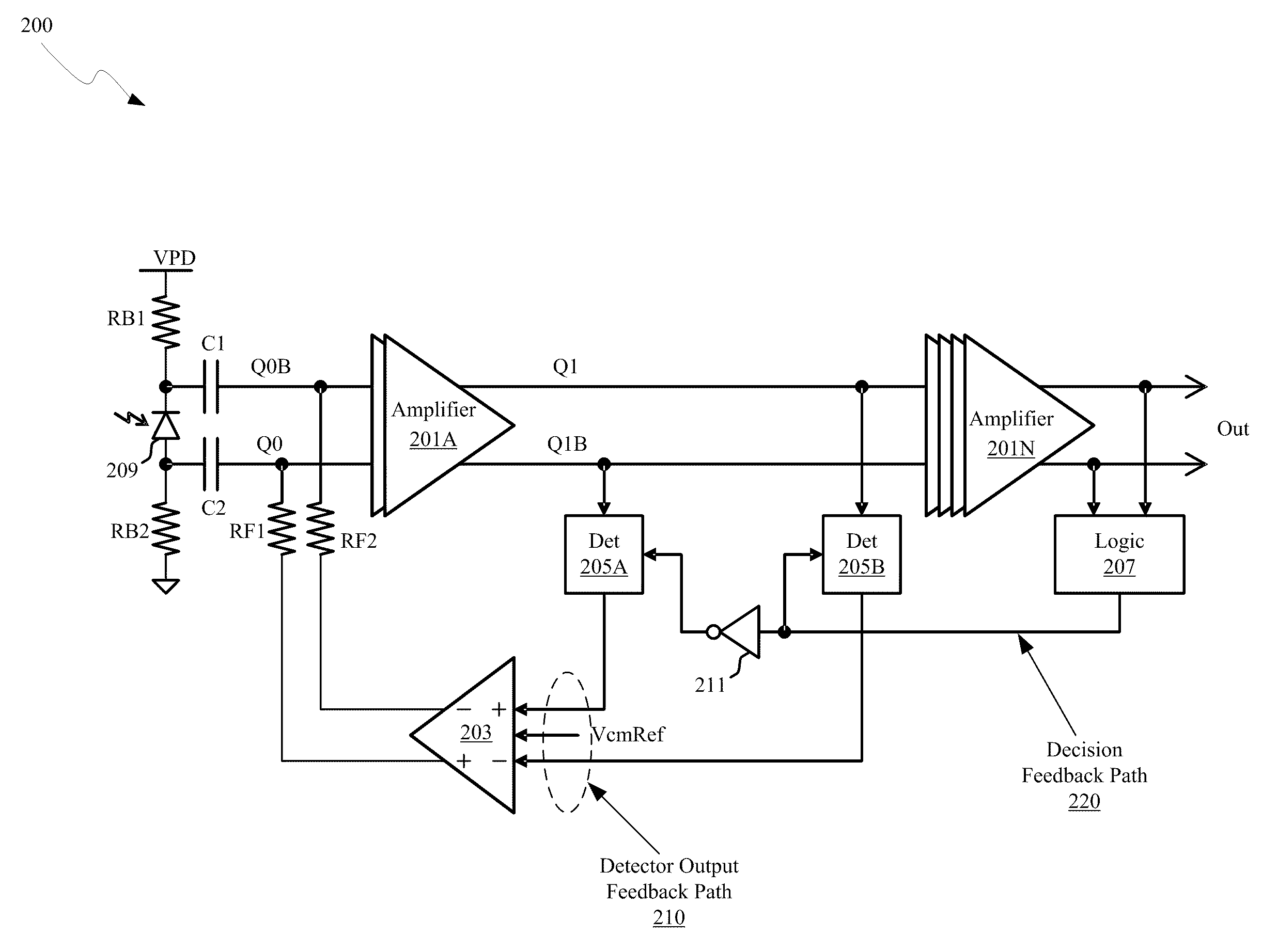
[0017]Certain aspects of the invention may be found in a method and system for optoelectronic receivers for uncoded data. Exemplary aspects of the invention may comprise amplifying received electrical signals in a signal amplifier comprising one or more differential gain stages with two or more signal detectors coupled to outputs of one or more of the differential gain stages. A value of a first sampled output voltage of a differential gain stage may be tracked and a value of a second sampled output voltage of the gain stage may be held utilizing the two or more signal detectors. A difference between the tracked value of the first sampled output voltage and the held value of the second sampled output voltage may be amplified in a feedback path of the differential gain stage, wherein the feedback path enables the dynamic configuration of a decision level for the signal amplifier. The received electrical signals may be generated from a received optical signal, which may be received ut...


PUM


Abstract

A method and system for optoelectronic receivers for uncoded data are disclosed and may include amplifying received electrical signals in a signal amplifier comprising differential gain stages with signal detectors coupled to the outputs. First and second output voltages may be tracked and held utilizing the signal detectors. A difference between the tracked and held value may be amplified in a feedback path of the gain stage, which enables the dynamic configuration of a decision level. The received electrical signals may be generated from an optical signal by a PIN detector, an avalanche photodiode, or a phototransistor. The electrical signal may be received from a read channel. The feedback path may comprise digital circuitry, including an A / D converter, a state machine, and a D / A converter. The detectors may comprise envelope detectors utilized to detect maximum or minimum voltages. The signal amplifier may be integrated in a photonically-enabled CMOS chip.

Description

CROSS-REFERENCE TO RELATED APPLICATIONS / INCORPORATION BY REFERENCE[0001]This application makes reference to and claims priority to U.S. Provisional Application Ser. No. 61 / 270,655 filed on Jul. 10, 2009, which is hereby incorporated herein by reference in its entirety.FEDERALLY SPONSORED RESEARCH OR DEVELOPMENT[0002][Not Applicable]MICROFICHE / COPYRIGHT REFERENCE[0003][Not Applicable]FIELD OF THE INVENTION[0004]Certain embodiments of the invention relate to signal processing. More specifically, certain embodiments of the invention relate to a method and system for single laser bidirectional links.BACKGROUND OF THE INVENTION[0005]As data networks scale to meet ever-increasing bandwidth requirements, the shortcomings of copper data channels are becoming apparent. Signal attenuation and crosstalk due to radiated electromagnetic energy are the main impediments encountered by designers of such systems. They can be mitigated to some extent with equalization, coding, and shielding, but thes...

Claims


Application Information

Patent Timeline
Patent Type & Authority Patents(United States)
IPC IPC(8): H04B10/60
CPCH03F3/08H04B10/6931H03F1/301
Inventor KUCHARSKI, DANIEL
Owner CISCO TECH INC
Why Eureka
Try Eureka