Supercharge Your Innovation With Domain-Expert AI Agents!

Method and system for control of communication equipment based on a bit error rate derived from a frame alignment signal

a communication equipment and frame alignment technology, applied in the direction of transmission monitoring, instruments, coding, etc., can solve the problems of not being able to correct for an unlimited number of data errors, often occurring errors during transmission of data, and exceeding the capability of fec error correction capability

Active Publication Date: 2013-01-22
INFINERA CORP
View PDF3 Cites 0 Cited by
  • Summary
  • Abstract
  • Description
  • Claims
  • Application Information

AI Technical Summary

Benefits of technology

The present disclosure provides a method and apparatus for receiving an optical signal, converting it to an electrical signal, and identifying a frame alignment signal in the series of bits. The bit error rate is determined based on the number of errors in the frame alignment signal and the corresponding series of bits, and the parameter associated with the optical component is adjusted accordingly. This allows for improved accuracy, reliability, and efficiency in signal conversion and performance of the optical component.

Problems solved by technology

Errors often occur during transmission of the data, such as a “1” bit may be received as a “0” bit and visa versa.
FEC, however, cannot correct for an unlimited number of errors present in the data.
Under certain circumstances, however, the BER may exceed the error correcting capability of the FEC.
For example, during start-up of the WDM optical communication systems noted above, various electrical or optical components in such systems may not be properly set to process the received optical signals, thereby resulting in excessively high bit error rates, e.g., greater than 10−3, which cannot be reduced by FEC.
Such high bit error rates are typically unacceptable for many telecommunication applications.

Method used


Image

  • Method and system for control of communication equipment based on a bit error rate derived from a frame alignment signal
  • Method and system for control of communication equipment based on a bit error rate derived from a frame alignment signal
  • Method and system for control of communication equipment based on a bit error rate derived from a frame alignment signal

Examples


Embodiment Construction

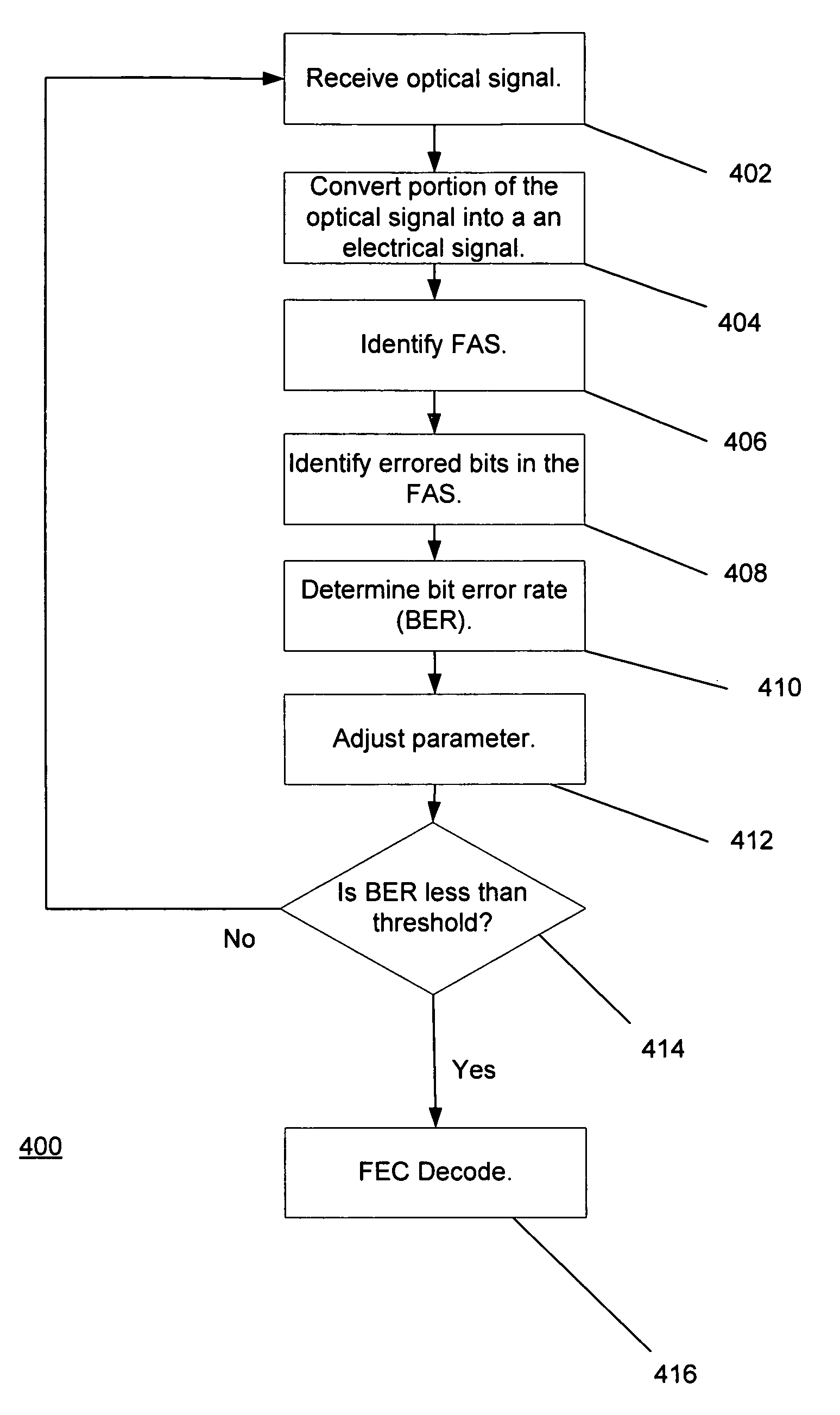
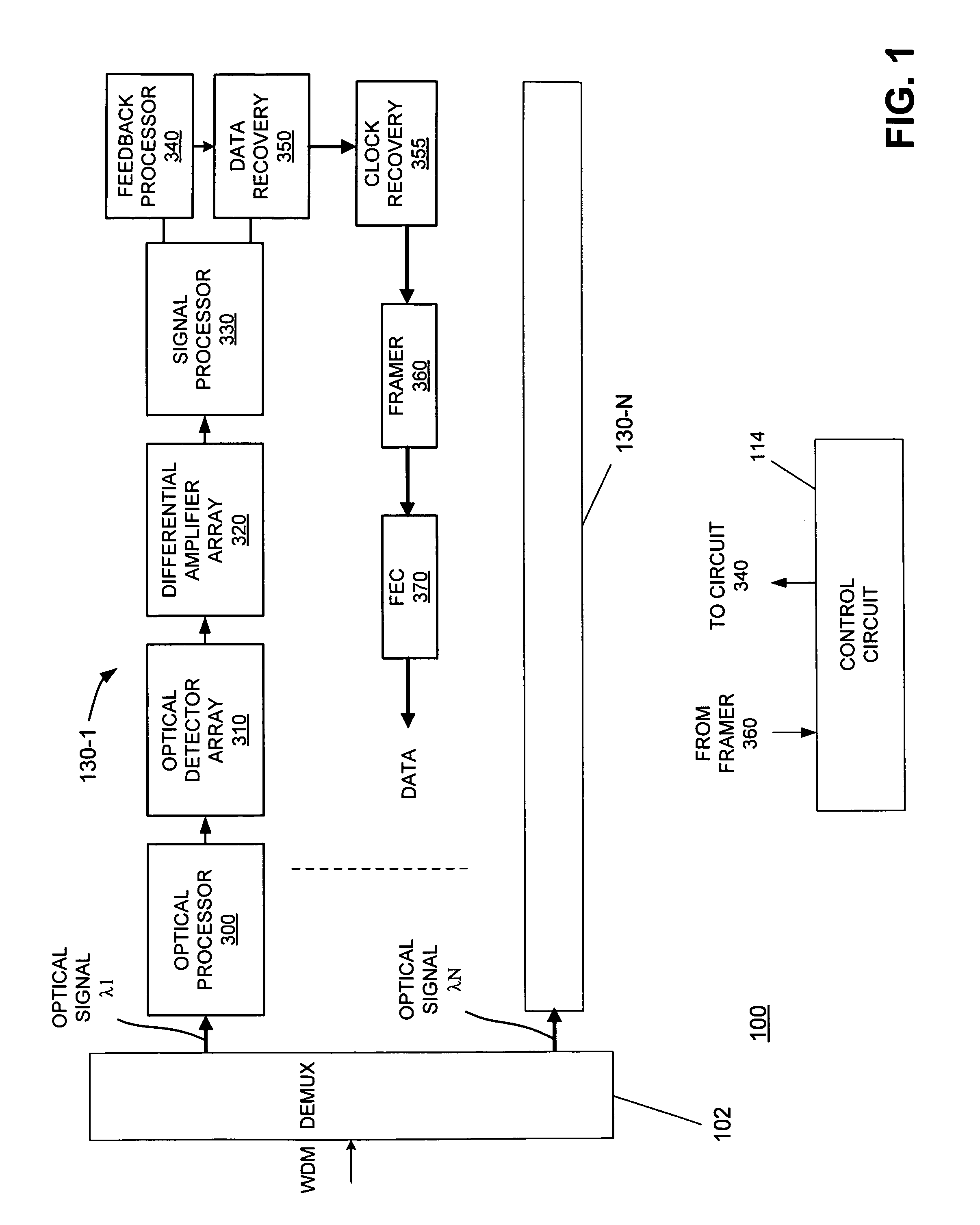
[0015]As generally understood, data is often transmitted to a receiver in frames that include header and payload portions. The payload typically carries the data itself and the header includes monitoring and network management information, for example. The header also includes a series of predetermined bits that indicates the start of a frame (often referred to as a frame alignment signal). Although the frame alignment signal may include errored bits, if the number of errored bits is below a predetermined amount, the frame alignment signal may still be recognized. Consistent with the present disclosure, circuitry may be provided in the receiver that can determine a bit error rate (BER) by dividing the number of errored bits by the number of bits in the frame alignment signal. Accordingly, although an optical signal may be severely degraded and forward error correction (FEC) cannot be performed, a BER may be obtained if the frame alignment signal can be identified. In addition, the b...


PUM


Abstract

Consistent with the present disclosure, circuitry may be provided in an optical receiver that can determine a bit error rate (BER) associated with an incoming signal by dividing the number of errored bits in a frame alignment signals (FAS) by the number of bits in the FAS. Accordingly, although an optical signal may be severely degraded and forward error correction (FEC) cannot be performed, a BER may be obtained if the FAS can be identified. The BER can then be used in a feedback loop to control various optical or electrical components in the receiver to improve or reduce the BER to a level, for example, at which FEC can be performed.

Description

BACKGROUND[0001]Optical communication systems are known in which multiple optical signals carrying data, for example, propagate along an optical fiber from a transmitter to a receiver. In such optical communication systems, often referred to as wavelength division multiplexed (WDM) optical communication systems, each optical signal has a corresponding one of a plurality of wavelengths. In the receiver, the optical signals are filtered or demultiplexed and converted into corresponding electrical signals which also carry the data. The data is typically in digital form and thus constitutes a series of binary bits. Errors often occur during transmission of the data, such as a “1” bit may be received as a “0” bit and visa versa. In order to correct for such errors, the data is coded in the transmitter in accordance with a so-called forward error correction (FEC) code, whereby additional bytes are added to the data and then manipulated by known algorithms. The encoded data is then transmi...

Claims


Application Information

Patent Timeline
Patent Type & Authority Patents(United States)
IPC IPC(8): G06F11/00
CPCH04L1/0045H04L1/203H04J14/0221
Inventor BIALKOWSKI, JANSRIDHARAN, SATISH K.CHIANG, TING-KUANG
Owner INFINERA CORP
Features
  • R&D
  • Intellectual Property
  • Life Sciences
  • Materials
  • Tech Scout
  • Unparalleled Data Quality
  • Higher Quality Content
  • 60% Fewer Hallucinations
Learn More