Structure constructed using precast members and method of constructing the same

a technology of precast members and construction methods, which is applied in the direction of building roofs, parkings, building repairs, etc., can solve the problems of reducing construction efficiency, reducing construction efficiency, and difficult to completely pour fresh concrete into every portion of the junction of reinforcing bars, so as to improve construction efficiency, enhance structural strength of the junction between pc walls and pc slabs, and reduce construction time.

Active Publication Date: 2013-01-29
LEE WAN YOUNG
View PDF18 Cites 14 Cited by
  • Summary
  • Abstract
  • Description
  • Claims
  • Application Information

AI Technical Summary

Benefits of technology

[0013]In a structure constructed using PC members and a method of constructing the structure according to the present invention, connection reinforcing bars, which protrude from PC wall members of PC walls, and open reinforcing bars, which extend from PC slab members of PC slabs, are overlapped and integrated with each other in slab areas by connection concrete, which is cast at a construction site. Therefore, the range of a junction between each PC wall and the corresponding PC slab is prevented from being concentrated at one position, but is dispersed over the area of the corresponding slabs. Thus, working conditions for conducting the operation of coupling the PC slabs to the PC walls are improved, and construction efficiency is improved.
[0014]Furthermore, the range within which the connection reinforcing bars of the PC wall members and the open reinforcing bars of the PC slab members are overlapped with each other is relatively large, so that connection concrete to be cast at a construction site can be fully and closely charged into the reinforcing bar junction, thus preventing an opening from being formed in the cross-section of the reinforcing bar junction. Therefore, there is an advantage in that the structural strength of the junctions between the PC walls and the PC slabs is enhanced.
[0015]In addition, in the present invention, the PC slabs are coupled to the PC walls by a construction method in which connection concrete is cast at a construction site using supporting molds, which are removably mounted to the PC wall members of the PC walls at corresponding positions, in a state in which the PC slab members of the PC slabs are supported on the corresponding supporting molds. Hence, the PC slab members of the PC slabs can be coupled to the PC wall members of the PC walls at the same time, so that the construction time can be markedly reduced, and, as well, a process of installing wooden concrete forms, which is a major factor that increases the amount of work in the conventional technique, is not required when the PC slabs are coupled to the PC walls, thus reducing the number of workers and construction costs.

Problems solved by technology

First, because the conventional technique has a complex construction, in which the upper and lower connection parts of the wall reinforcing bars of the upper and lower PC wall panels and the mounting parts of the slab reinforcing bars of the half PC slab panels are gathered at one junction, that is, in the reinforcing bar junction, the work of constructing the PC walls and the PC slabs is more difficult, thus markedly reducing construction efficiency.
In addition, it is difficult to completely pour fresh concrete into every portion of the reinforcing bar junction, at which the upper and lower connection parts of the wall reinforcing bars of the upper and lower PC wall panels and the slab reinforcing bars of the half PC slab panels are complicatedly coupled to each other.
Thus, an opening may be undesirably formed in the cross-section of the reinforcing bar junction, with the result that the structural strength is decreased.
As a result, there is a problem in that the time required to construct the structure using the PC members is excessively increased.

Method used


Image

  • Structure constructed using precast members and method of constructing the same
  • Structure constructed using precast members and method of constructing the same
  • Structure constructed using precast members and method of constructing the same

Examples


Embodiment Construction

[0038]Hereinafter, a structure constructed using PC (precast) members according to a preferred embodiment of the present invention will be described in detail with reference to the attached drawings.

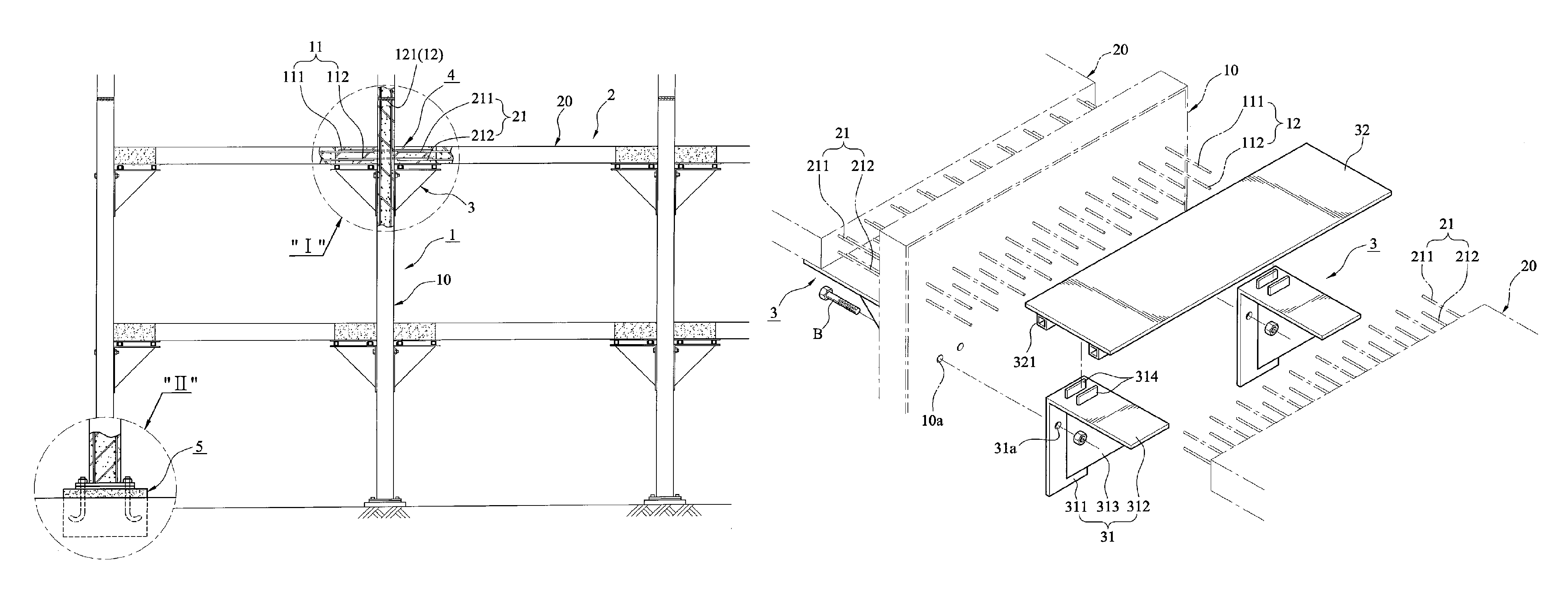
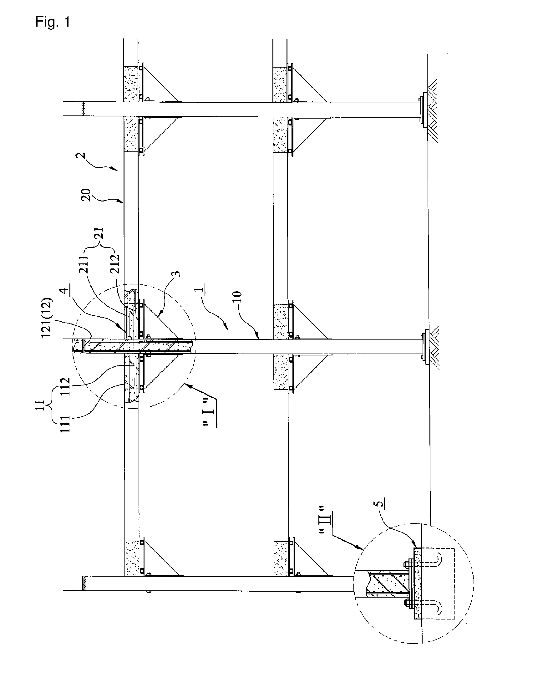
[0039]The structure constructed using the PC members according to the present invention includes PC walls 1, each of which is constructed using PC wall members 10, PC slabs 2, each of which is constructed using PC slab members 20, supporting molds 3, which are removably mounted to the PC wall members 10 of the PC walls 1, and connection concrete 4, which couples the PC walls 1 to the corresponding PC slabs 2.

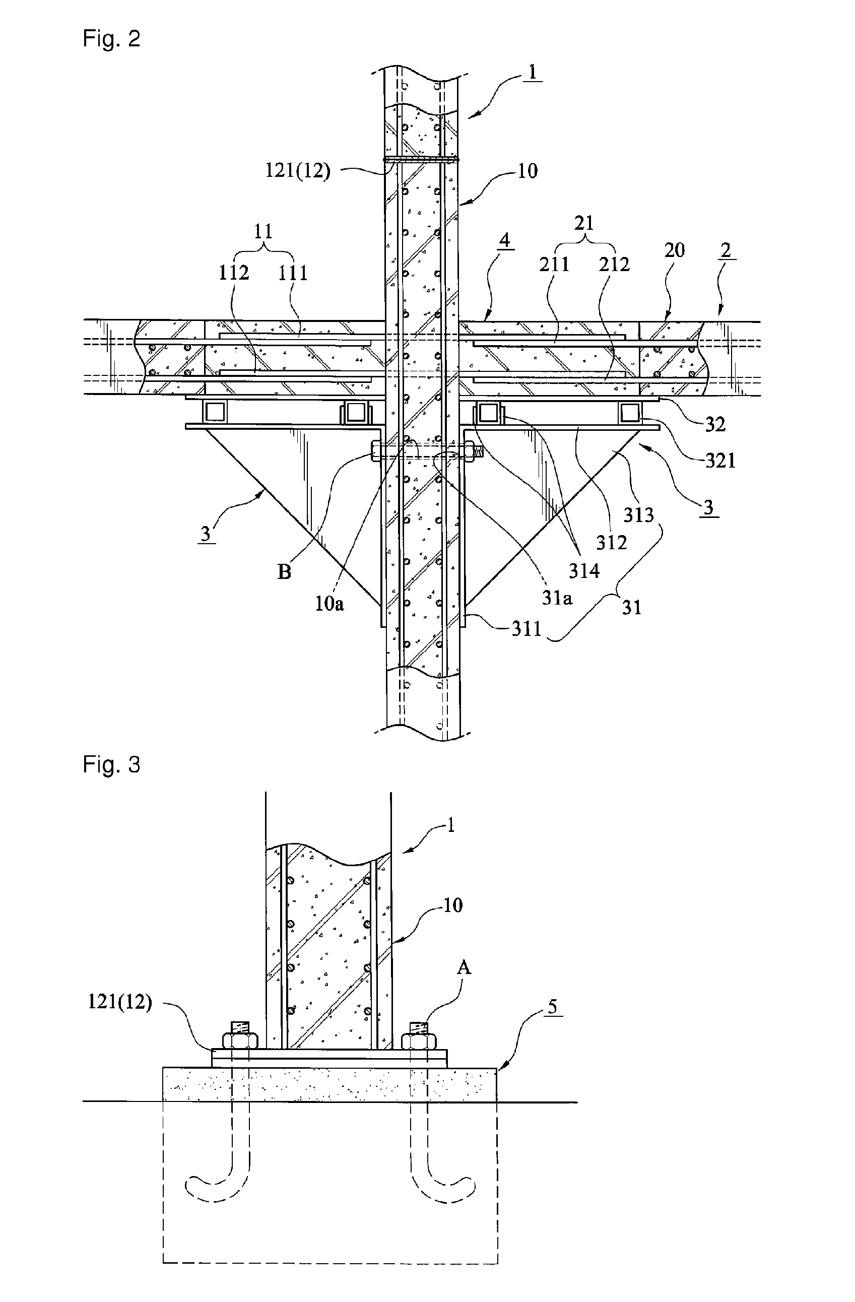
[0040]As shown in FIGS. 1 through 3, each PC wall 1 is constructed by consecutively placing the PC wall members 10 on top of one another on a corresponding base 5, which is previously constructed at a given construction position.

[0041]Every PC wall member 10 is a concrete plate body, which is produced in a factory. Each PC wall member 10 has connection reinforcing bars 11, which exte...


PUM


Abstract

The present invention provides a structure constructed using PC members and a method of constructing the structure. In the present invention, each of PC wall members (10) of PC walls (1) has connection reinforcing bars (11) at predetermined positions. Each of PC slab members (20) of PC slabs (2) has open reinforcing bars (21), which protrude from the PC slab member (20). Supporting molds (3) are mounted to the PC wall members (10) at positions just below the connection reinforcing bars (11), so that the PC slab members (20) are placed on the supporting molds (3), such that the connection reinforcing bars (11) are overlapped with the corresponding open reinforcing bars (21) in slab areas, and connection concrete (4) is cast at a construction site such that the connection reinforcing bars (11) and the open reinforcing bars (21) are embedded in the connection concrete (4), thus integrating the PC walls (1) and the PC slabs (2) with each other.

Description

RELATED APPLICATIONS[0001]This application is a 371 application of International Application No. PCT / KR2007 / 006128, filed Nov. 30, 2007, which in turn claims priority from Korean Patent Application No. 10-2007-0083960, filed Aug. 21, 2007, both of which are incorporated herein by reference in their entireties.TECHNICAL FIELD[0002]The present invention relates, in general, to the construction of structures, such as apartment buildings and office buildings, and, more particularly, to a structure constructed using PC (precast) members, in which PC walls and PC slabs are integrated with each other using connection concrete in slab areas, and a method of constructing such a structure.BACKGROUND ART[0003]Recently, a method of constructing a structure using PC members, which are manufactured in a factory and carried to a construction site, was proposed and has been effectively used at construction sites to construct apartment buildings and office buildings.[0004]For example, a representati...

Claims


Application Information

Patent Timeline
Patent Type & Authority Patents(United States)
IPC IPC(8): E04B1/04E04B1/41
CPCE04B1/04E04B5/023E04B5/046E04B5/43E04B1/02E04B1/30E04B5/02
Inventor LEE, WAN YOUNG
Owner LEE WAN YOUNG
Why Eureka
Try Eureka