
Image sensing apparatus and imaging system

a technology of image sensing apparatus and imaging system, which is applied in the direction of color television details, television system details, television systems, etc., can solve the problem of different noise levels generated by a change in the counted value of the counter, and achieve the effect of suppressing mixing

Inactive Publication Date: 2013-01-29
CANON KK
View PDF39 Cites 29 Cited by
  • Summary
  • Abstract
  • Description
  • Claims
  • Application Information

AI Technical Summary

Benefits of technology

[0008]It is an aim of the present invention to suppress mixing, in a pixel signal, of noise generated upon a change of the counted value of a counter in the horizontal scanning period.
[0012]The present invention can suppress mixing, in a pixel signal, of noise generated upon a change of the counted value of a counter in the horizontal scanning period.

Problems solved by technology

In particular, the level of noise generated upon a change of the counted value of the counter is different between a pixel signal output at the timing when the counted value is carried, and a pixel signal output at another timing.

Method used


Image

  • Image sensing apparatus and imaging system
  • Image sensing apparatus and imaging system
  • Image sensing apparatus and imaging system

Examples


first embodiment

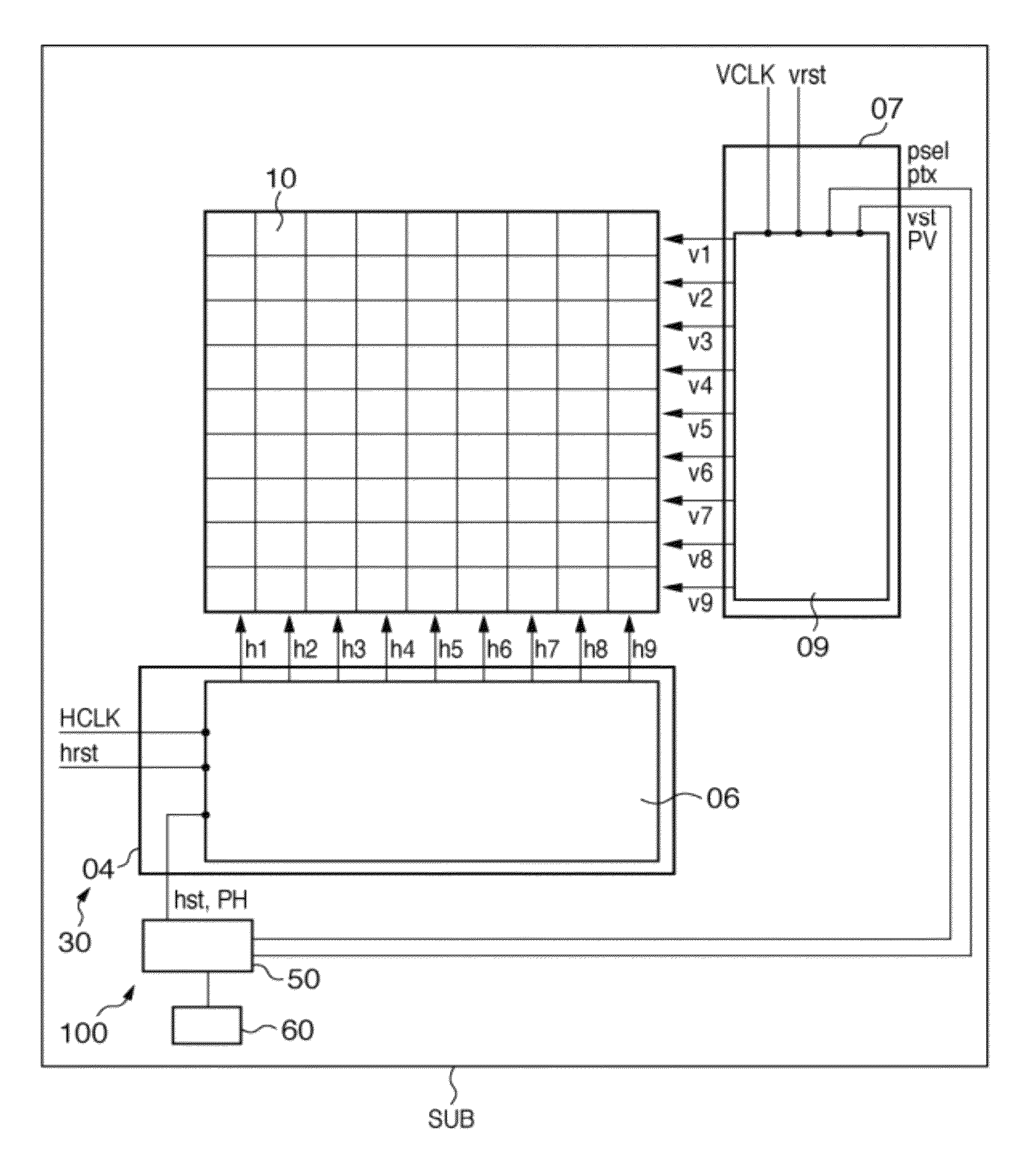
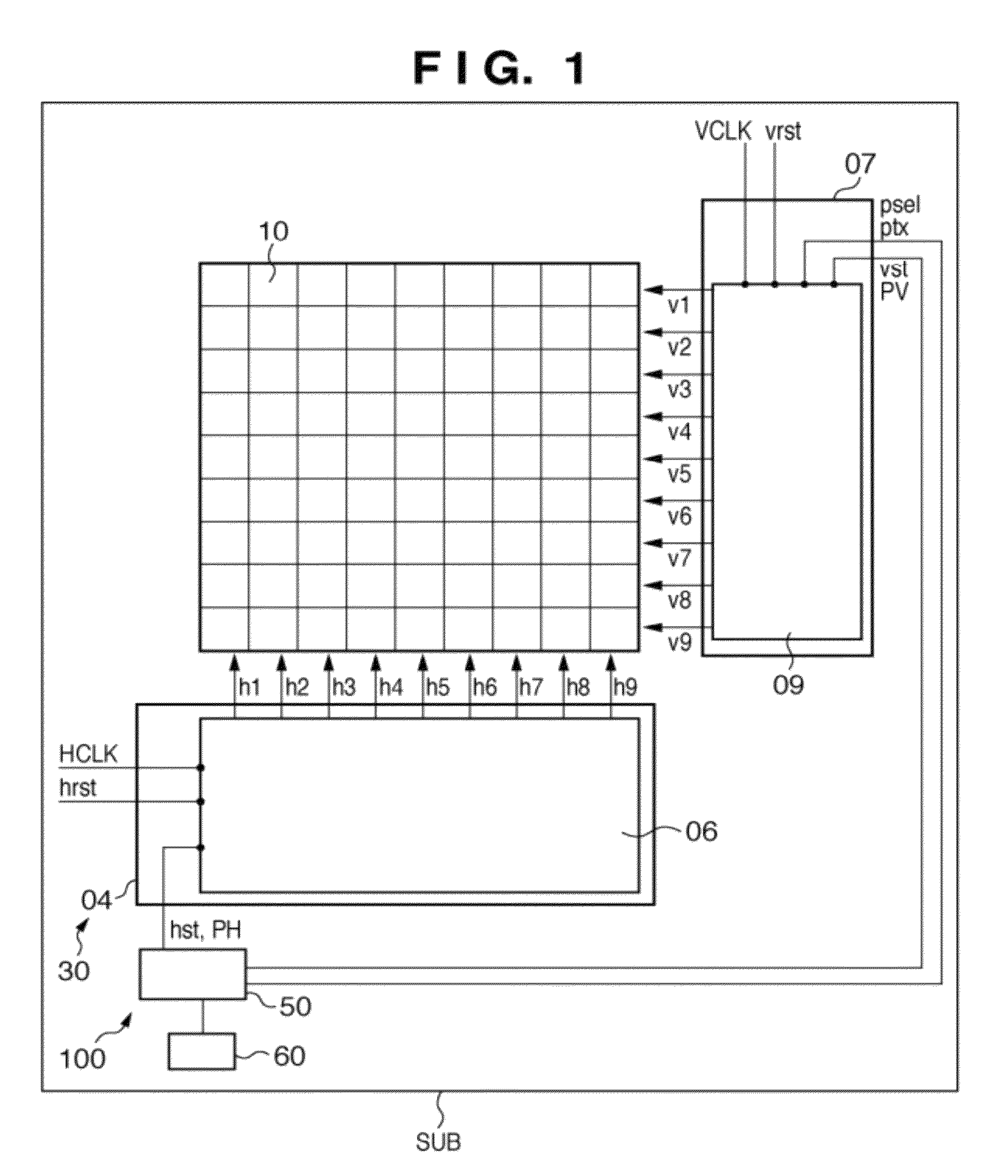
[0082]As described above, even when the control signals psel and ptx are supplied to the vertical scanning circuit during the horizontal scanning period in the image sensing apparatus including an on-chip counter circuit which is formed on a single semiconductor substrate, the counter circuit can be stopped during the horizontal scanning period. This can reduce the influence, on a pixel signal, of noise generated upon carrying the counter value, that is, suppress mixing, in a pixel signal, of noise generated upon a change of the counted value of a counter in the horizontal scanning period.

[0083]In horizontal extraction and readout for each pixel, degradation of a pixel signal caused by the operation of the counter circuit can be reduced, implementing a high-quality image extraction function.

[0084]It should be noted that an OB clamp pulse PBLK for controlling an A / D converter which A / D-converts an image signal in the image sensing apparatus 100 is a pulse for controlling the positio...

second embodiment

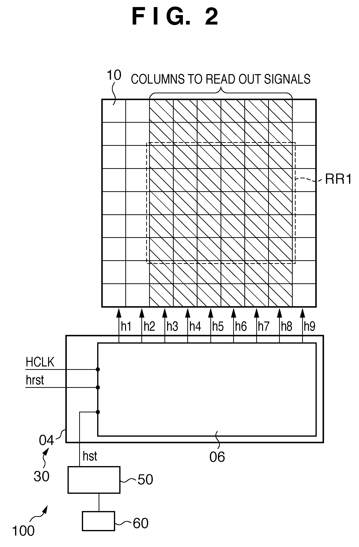
[0150]In this way, when the control signal hst is supplied to the horizontal scanning circuit during the horizontal scanning period in the image sensing apparatus including an on-chip counter circuit, the counter circuit can be stopped during the horizontal scanning period. This can reduce the influence, on a pixel signal, of noise generated upon carrying the counter value, that is, suppress mixing, in a pixel signal, of noise generated upon a change of the counted value of a counter in the horizontal scanning period.

[0151]In horizontal extraction and readout for each pixel, degradation of a pixel signal caused by the operation of the counter circuit can be reduced, implementing a high-quality image extraction function.

[0152]The shift register 32 receives the second start signal hst in the period TP1 at a timing (e.g., timing T12 in FIG. 12) to start scanning the readout region RR1 from the start of the period TP2. With this setting, the period until scanning of the readout region ...


PUM


Abstract

An image sensing apparatus comprising on a single semiconductor substrate: a pixel array; a vertical scanning unit; a horizontal scanning unit; a counter which starts a counting operation to count the number of the clocks before a start of the first period, and stops the counting operation before a start of the second period during the first period; and a generation unit which generates a first control signal for causing the vertical scanning unit to drive a pixel, the generation unit including a signal generation unit which generates a second control signal in accordance with the counted value output from the counter, and a delay unit which delays the second control signal to generate the first control signal and output the first control signal to the vertical scanning unit.

Description

BACKGROUND OF THE INVENTION[0001]1. Field of the Invention[0002]The present invention relates to an image sensing apparatus and imaging system.[0003]2. Description of the Related Art[0004]There has conventionally been proposed an image sensing apparatus having a pixel array (see Japanese Patent Laid-Open No. 2001-045383). According to the technique disclosed in Japanese Patent Laid-Open No. 2001-045383, a shift register for scanning the respective rows or columns of the pixel array is formed from a plurality of circuit blocks. A decoder circuit for selecting one of the circuit blocks is arranged on the preceding stage of the shift register. By selecting a circuit block by the decoder circuit, scanning of pixels can start for each pixel block including a plurality of pixels in the pixel array.[0005]Recently, image sensing apparatuses such as a video camera and still camera require a high-precision electronic anti-shock (camera shake correction) function. As a technique for implementi...

Claims


Application Information

Patent Timeline
Patent Type & Authority Patents(United States)
IPC IPC(8): H04N5/335H04N5/365H04N5/369H04N5/376
CPCH04N5/361H04N5/3658H04N5/3765H04N25/63H04N25/677H04N25/745
Inventor SONODA, KAZUHIROTAKENAKA, SHINTARONODA, TOMOYUKIITANO, TETSUYA
Owner CANON KK
Learn More