
Piezoelectric speaker, speaker apparatus, and tactile feedback apparatus

a technology of speaker and tactile feedback, which is applied in the direction of piezoelectric/electrostrictive transducers, instruments, transducer types, etc., can solve the problems of deteriorating the visibility of the display screen, troublesome operation, and deteriorating the visual quality of the device such as a cellular phone, and achieves excellent transparency, enhanced piezoelectricity, and great piezoelectric constant stability

Active Publication Date: 2013-01-29
MURATA MFG CO LTD
View PDF59 Cites 16 Cited by
  • Summary
  • Abstract
  • Description
  • Claims
  • Application Information

AI Technical Summary

Benefits of technology

The present invention describes a piezoelectric speaker and a tactile feedback apparatus that uses it. The invention allows for the speaker to vibrate and make sound even when its entire circumference is fixed. This increases the design flexibility of the speaker, making it suitable for various positions and conformations. Additionally, the invention uses the piezoelectric speaker as a vibrating plate, which eliminates the need for an actuator and makes the tactile feedback apparatus easy to configure. The vibration is transmitted to the fingertip through the touch panel, providing a unique experience for the user.

Problems solved by technology

However, mounting the transparent speaker on the display screen as being bent not only deteriorates the visual quality of the device such as a cellular phone, but also sometimes deteriorates visibility of the display screen, since things around it are reflected on the transparent speaker.
Moreover, in the transparent speaker disclosed in Patent Document 1, the side face of the vibration plate is greatly open, so that dusts or other smudges are easy to enter, and once they enter, removing them is a troublesome operation.
Further, a protection plate for protecting the display screen and the transparent speaker cannot be shared.

Method used


Image

  • Piezoelectric speaker, speaker apparatus, and tactile feedback apparatus
  • Piezoelectric speaker, speaker apparatus, and tactile feedback apparatus
  • Piezoelectric speaker, speaker apparatus, and tactile feedback apparatus

Examples


first embodiment

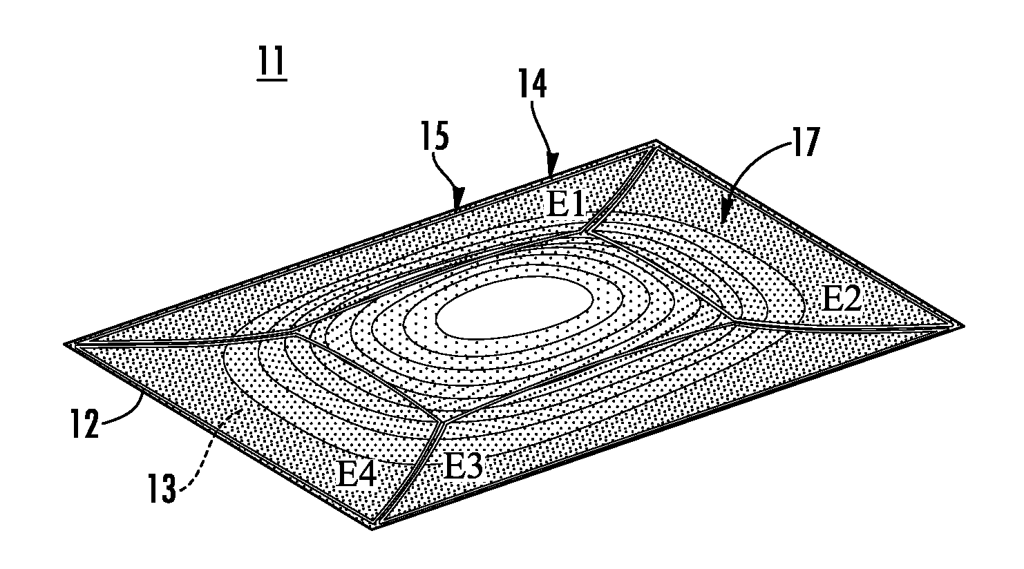
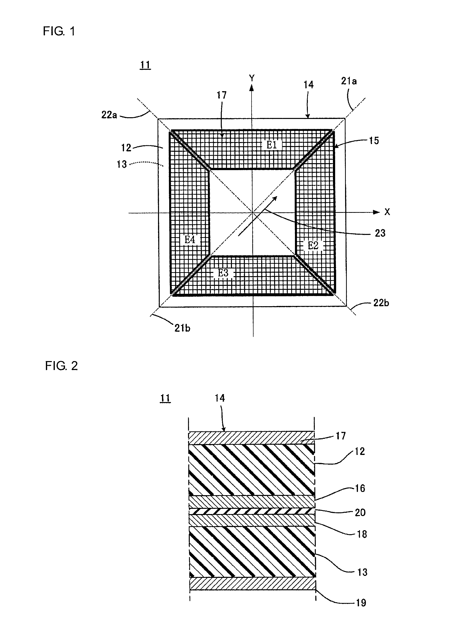
[0121]FIG. 1 is a plan view illustrating a piezoelectric speaker 11 according to the present invention. FIG. 2 is a sectional view illustrating a part of the piezoelectric speaker 11 illustrated in FIG. 1 as being enlarged.

[0122]The piezoelectric speaker 11 includes a laminated body 14 having two square sheets 12 and 13, each being made of a polymer, bonded to each other. In the present embodiment, the two sheets 12 and 13 are both piezoelectric sheets having a predetermined stretching axis and made of a chiral polymer. The detail of the piezoelectric sheet having the predetermined stretching axis and made of the chiral polymer will be described later.

[0123]Vibration regions 15 that should be vibrated are provided on the respective piezoelectric sheets 12 and 13. First and second electrodes 16 and 17 are provided with the same pattern on first and second main surfaces, which are opposite to the vibration regions 15 on the piezoelectric sheet 12, in order to apply voltage to the piez...

second embodiment

[0181]FIG. 10 is a diagram corresponding to FIG. 8 for describing the present invention. In FIG. 10, the components corresponding to those illustrated in FIG. 8 are identified by the same symbols, and the repeated description will not be made.

[0182]A piezoelectric speaker 11a illustrated in FIG. 10 is characterized in that it does not have a bimorph structure, but has a unimorph structure. Specifically, although not clearly illustrated in FIG. 10, a laminated body 14a provided to a piezoelectric speaker 11a has a structure in which two sheets, which are made of a polymer, are bonded to each other, and only one sheet of two sheets is a piezoelectric sheet having electrodes formed on both main surfaces. As for the other sheet, even when it is made of the PLLA, for example, an electrode is not formed thereon. Since this sheet does not need to have piezoelectricity, it may be made of a polymer having high transparency other than the PLLA, such as polymethylmethacrylate, polycarbonate, o...

third embodiment

[0184]FIG. 11 is a diagram corresponding to FIG. 8 for describing the present invention. FIG. 8 is a perspective view, while FIG. 11 is a plan view. In FIG. 11, the components corresponding to those illustrated in FIG. 8 are identified by the same symbols, and the repeated description will not be made.

[0185]The piezoelectric speaker 11 illustrated in FIG. 8 has a square shape as well illustrated in FIG. 1, but a piezoelectric speaker 11b illustrated in FIG. 11 has a rectangular shape. In this manner, even in the piezoelectric speaker 11b having the rectangular shape, the substantially similar displacement can be produced as illustrated in FIG. 11. The piezoelectric speaker 11b having the rectangular shape is advantageously used in a cellular phone as described below.

[0186]As illustrated in FIG. 12, most of cellular phones 31 used in Japan have a rectangular display surface 32. Since the piezoelectric speaker according to the present invention can be made transparent, it can be confi...


PUM


Abstract

A piezoelectric speaker that includes an electrode formed on opposing main surfaces of a piezoelectric sheet having a predetermined stretching axis and made of a chiral polymer. The electrode is divided into four electrode portions by a plurality of dividing lines extending in a radiation direction. The four electrode portions are distributed along the outer peripheral portion except for the central portion of a vibration region. Voltage is applied to the respective four electrode portions in such a manner that electric field vectors generated in the thickness direction of the piezoelectric sheet direct in opposite directions between the adjacent ones of four sheet portions of the piezoelectric sheet to which voltage is applied by the electrode portions.

Description

CROSS REFERENCE TO RELATED APPLICATIONS[0001]The present application is a continuation of International Application No. PCT / JP2009 / 050236, filed Jan. 9, 2009, which claims priority to Japanese Patent Application No. JP2008-140977, filed May 29, 2008, the entire contents of each of these applications being incorporated herein by reference in their entirety.TECHNICAL FIELD[0002]The present invention relates to a piezoelectric speaker, a speaker apparatus, and a tactile feedback apparatus, and more particularly to a piezoelectric speaker configured to include a piezoelectric sheet made of a polymer, which exhibits piezoelectricity when it is stretched, such as polylactic acid, and a speaker apparatus and a tactile feedback apparatus configured by using the same.BACKGROUND ART[0003]For example, Japanese Unexamined Patent Publication No. 2003-244792 (Patent Document 1) discloses a transparent piezoelectric film speaker is mounted on a display screen of a cellular phone as being bent in o...

Claims


Application Information

Patent Timeline
Patent Type & Authority Patents(United States)
IPC IPC(8): H04R17/00G06F3/041
CPCH04R17/005H01L41/193H10N30/857
Inventor ANDOH, MASAMICHIKURETAKE, SATOSHI
Owner MURATA MFG CO LTD
Learn More