Method and apparatus for protecting RFID tags from power analysis

a technology for power analysis and rfid tags, applied in digital transmission, liquid/fluent solid measurement, instruments, etc., can solve the problems of difficult operation and even higher power consumption, and achieve the effect of reducing the number of power consumption information

Inactive Publication Date: 2013-01-29
YEDA RES & DEV CO LTD
View PDF9 Cites 13 Cited by
  • Summary
  • Abstract
  • Description
  • Claims
  • Application Information

AI Technical Summary

Benefits of technology

[0013]The present invention presents a cheap and effective solution for protecting RFIDs, which is perhaps the most compatible with current RF front ends found on tags. According to the inventive concept, a separation is created of the power supply from the power consumption by use of a double-buffering power supply mechanism consisting of a pair of capacitors switched by power transistors. At any stage in time, one capacitor is charged by the reader's field while the other is being discharged by the circuit. With appropriate design, the present invention can almost eliminate the power consumption information. Moreover, this design involves changes only to the RF front-end of the tag, making it the quickest to roll out. To make this countermeasure more cost effective, large flat capacitors can be attached to the plastic carrier next to the printed antenna. Note that unlike the case of smart cards, power analysis of RFID tags is likely to be carried out remotely (e.g., without opening in the store the product enclosure in which the RFID tag is placed) and thus, one is less concerned about an attacker cutting off the capacitors to get around the countermeasure. Tags using this protective mechanism still have to take care that power consumption does not leak out through the intentional backscatter modulation mechanism, which has to come out of the circuit proper and connect to the antenna.
[0014]Another major difference is that smart cards do not try to economize their power consumption, and with newer more powerful chips with security coprocessors, the power consumption gets even higher. It is thus difficult to run them from the tiny amount of power stored in a small capacitor. In contradistinction, RFID's get their power from the electromagnetic field around them, so they use very little power in order to be operable from a reader which is several meters away. This makes the protection technique more suitable for RFID tags than for smart cards.
[0015]Accordingly the present invention concerns a novel apparatus and method employed for protecting an RFID tag from attack. The method and apparatus of the invention protects RFID tags against simple and differential power attacks. The invention is particularly useful regarding inventory control systems and secure documents, such as e-passports.
[0022]Yet, it is still a further object of the invention to provide apparatus comprising: a) an RFID tag including an antenna, a power extraction circuit for generating power from an electromagnetic or magnetic field of a reader with which it is associated, and a computational circuit, b) at least two capacitors, each coupled between the power extraction circuit and the computational circuit, and c) switchover logic for alternately connecting the capacitors for at least one to discharge to power the computational circuit while at least one other is being charged by the power extraction circuit. The switchover logic can be such that the functions of the at least two capacitors are repeatedly reversed, and the RFID tag operates continuously. Also, the switchover logic can be such that the change of connection (switching of the capacitors) is triggered by the voltage across one of the capacitors exceeding or dropping below a certain threshold. Still further, the switchover logic can be such that the change of connection is triggered by a preselected event. Also, the switchover logic can be such that the change of connection is triggered by the voltage across at least one of the capacitors exceeding or dropping below a certain threshold at the beginning of a preselected event. In a preferred form of the invention, the switchover logic includes power transistors. A simple generalization of the present invention is to use three or more capacitors in such a way that at any time at least one of them is charging and at least one of the others is powering the computational element.

Problems solved by technology

Another major difference is that smart cards do not try to economize their power consumption, and with newer more powerful chips with security coprocessors, the power consumption gets even higher.
It is thus difficult to run them from the tiny amount of power stored in a small capacitor.

Method used


Image

  • Method and apparatus for protecting RFID tags from power analysis
  • Method and apparatus for protecting RFID tags from power analysis

Examples


Embodiment Construction

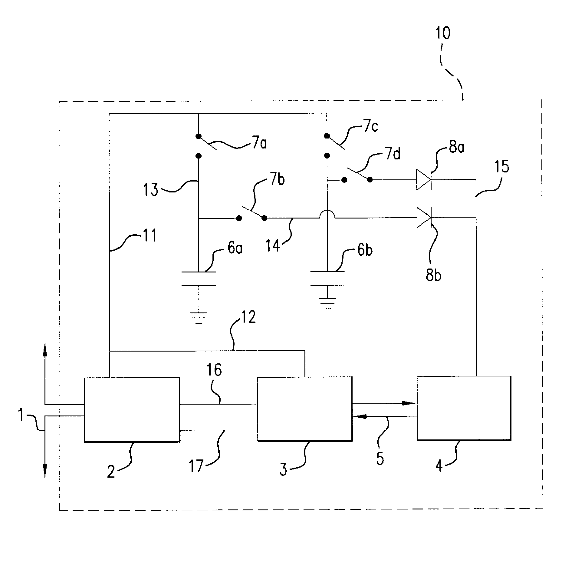
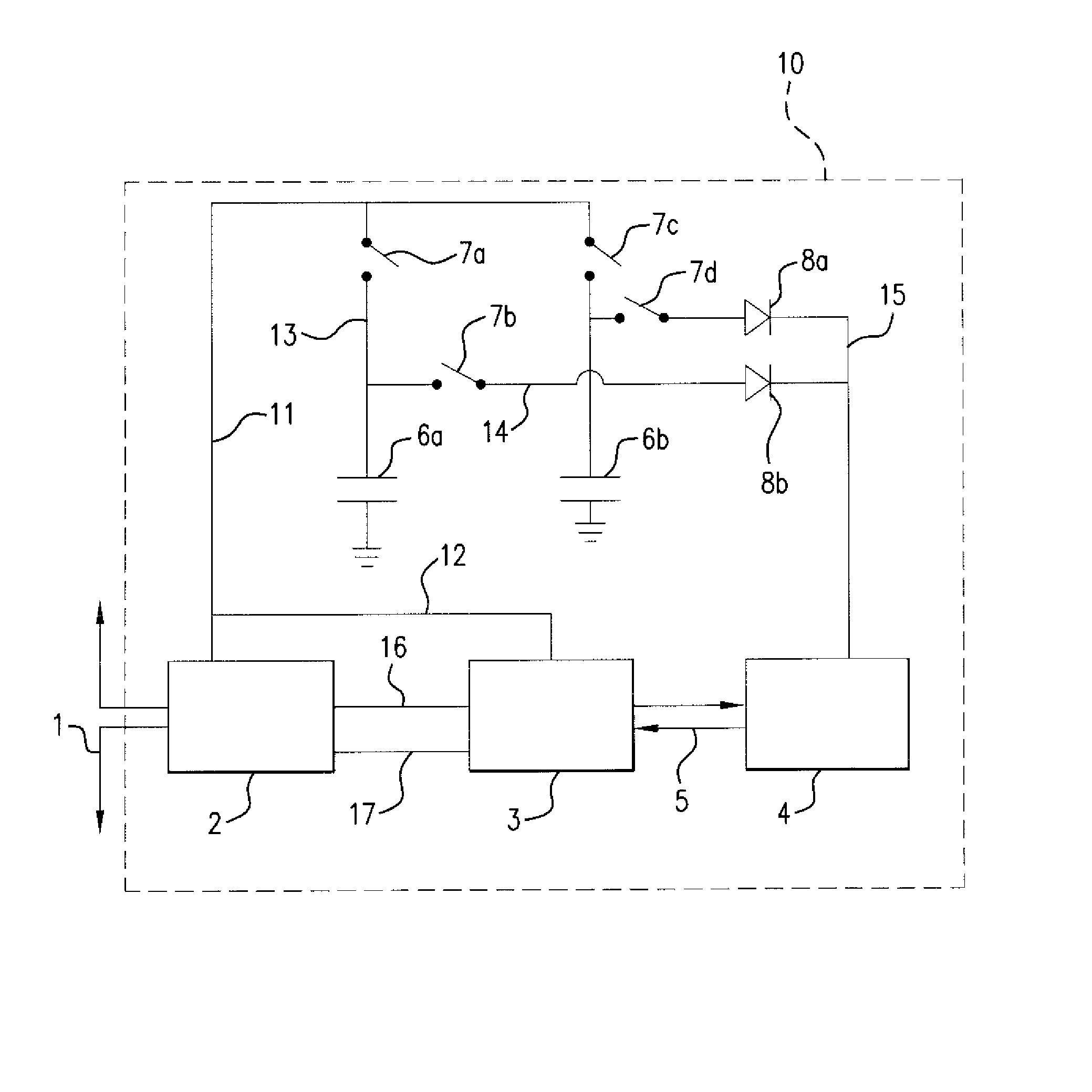
[0025]Referring now to the drawing, the preferred embodiment will now be described in detail. Shown is an RFID tag 10 which contains a power extraction circuit 2 connected to an antenna 1 that communicates with a tag reader (not shown) which has its own antenna and circuitry as is standard and known in the art. The antenna 1 is also coupled to a modulation-demodulation circuit 3 by leads 16 and 17 going through circuit 2. The circuit 3 is coupled to a logic and memory circuit 4, which is the computational element of tag 10. Data and control signals 5 pass between the circuits 3 and 4. The set-up thus far is standard for an RFID tag.

[0026]The object of the preferred embodiment is to allow circuit 4 to operate continuously without being directly powered by the power extraction circuit 2 during all or part of its computational function. To this end, two capacitors 6a and 6b are connected to ground on one side and to contacts of switches 7a and 7c, which switches 7a and 7c are connected...


PUM


Abstract

Method and apparatus for protecting RFID tags against power attacks by embedding two capacitors in an RFID tag and coupling to the RFID power extraction and computational circuitry to be operated so that at any given time during normal operation of the RFID tag one of them is coupled to the power extraction circuitry of the RFID tag and is storing energy that is being generated by the charge pump of the tag by sucking energy from the electromagnetic or magnetic field of a tag reader, and the other one is uncoupled from the power extraction circuitry of the RFID tag and is discharging and powering the computational element of the tag chip.

Description

BACKGROUND OF INVENTION[0001]1. Field of Invention[0002]The present invention relates to novel techniques, methods, and apparatus for protecting RFID tags from power analysis or from cryptanalytic attacks based on power analysis such as SPA or DPA when they are communicating with a tag reader.[0003]2. Prior Art[0004]Once considered merely as an upgrade to the humble optical barcode, passive RFID tags have been recently making gains both in their capabilities and in their planned applications. The regulatory bodies behind the tag standards are aware of security and privacy issues and have been urging tag makers to make their tags as secure as possible. There are even indications that RFID tags will soon implement full-fledged cryptographic functionality. A secure tag can enhance the privacy of consumers purchasing RFID-equipped products and the security of retailers using RFID technology, who need to know that tags are not tampered with. This is especially the case when discussing RF...

Claims


Application Information

Patent Timeline
Patent Type & Authority Patents(United States)
IPC IPC(8): G06F1/26G08B21/00G08B29/00G08B13/00G06F11/00
CPCG06K19/07363H04L9/0612H04L9/003H04L2209/12H04L2209/805
Inventor SHAMIR, ADI
Owner YEDA RES & DEV CO LTD
Why Eureka
Try Eureka