Internal combustion engine ignition device

a technology for ignition devices and combustion engines, applied in engine ignition, engine cooling apparatus, electrical apparatus, etc., can solve the problems of high thermal load on spark plugs, insufficient cooling methods used to date, and insignificant energy loss of spark plugs, etc., and achieve the effect of not significant energy loss

Active Publication Date: 2013-02-05
GE JENBACHER
View PDF23 Cites 16 Cited by
  • Summary
  • Abstract
  • Description
  • Claims
  • Application Information

AI Technical Summary

Benefits of technology

[0026]The heat to be dissipated from the spark plug sleeve is only a small fraction of the total engine cooling water heat (for example less than 3%) so that the required heat exchangers are relatively small and thus inexpensive and energy losses are not significant.
[0027]It can advantageously further be provided that the total surface area of the temperature control medium chamber on the side towards the spark plug (inward side) is of approximately the same size as the total internal surface area of the spark plug sleeve, into which the spark plug is screwed.

Problems solved by technology

The result of this however is that the spark plugs are subjected to a high thermal loading.
Therefore the methods of cooling used hitherto are in part no longer sufficient.
A disadvantage in that respect is inter alia that temperature control of the spark plug is always dependent on the temperature of the cooling medium in the cylinder head cooling cavity and the bores only extend in point configuration in the direction of the spark plug.
As a result, this does not involve uniform temperature control of the spark plug.
The disadvantage with that configuration is that the temperatures of the cooling passages always influence each other.

Method used


Image

  • Internal combustion engine ignition device
  • Internal combustion engine ignition device
  • Internal combustion engine ignition device

Examples


Embodiment Construction

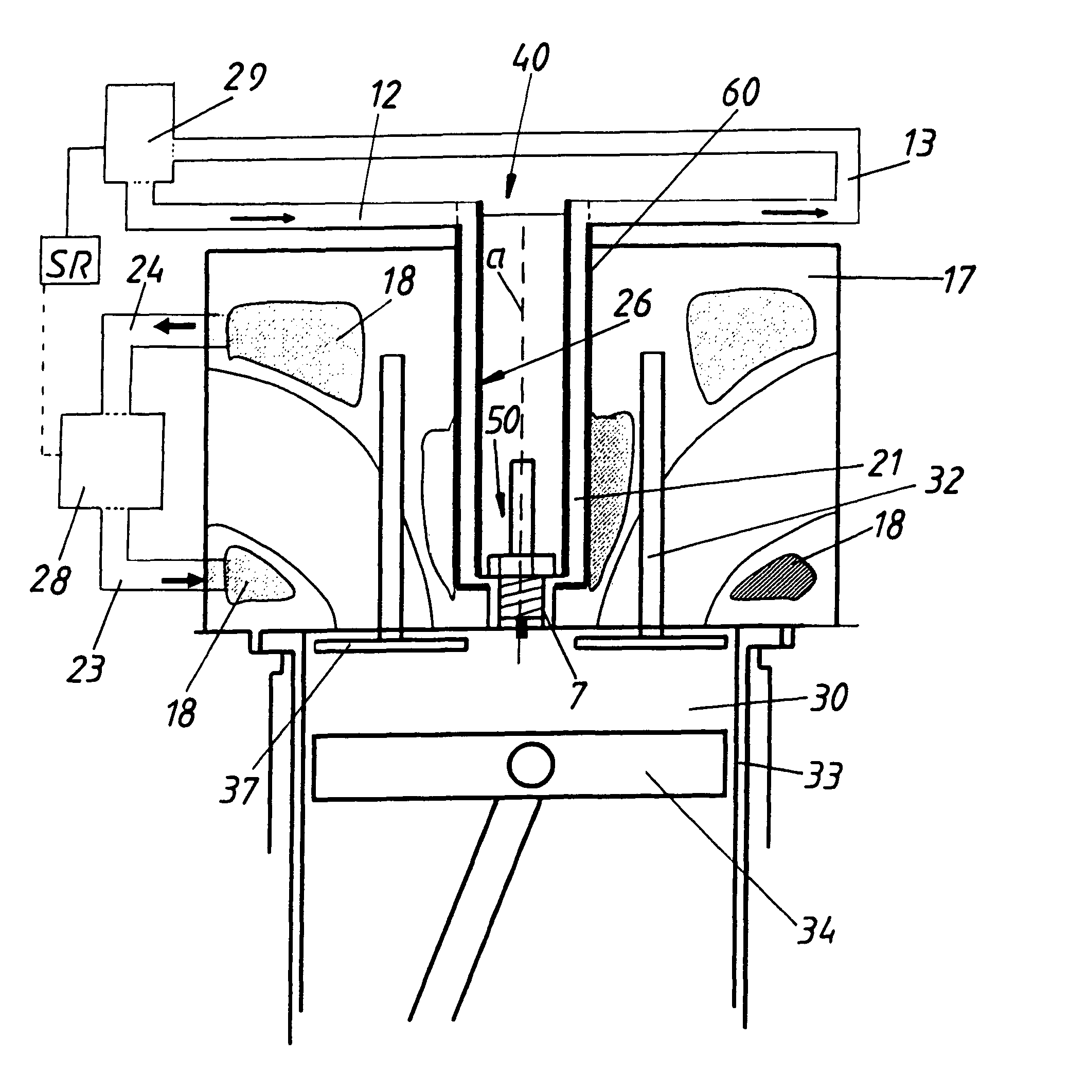
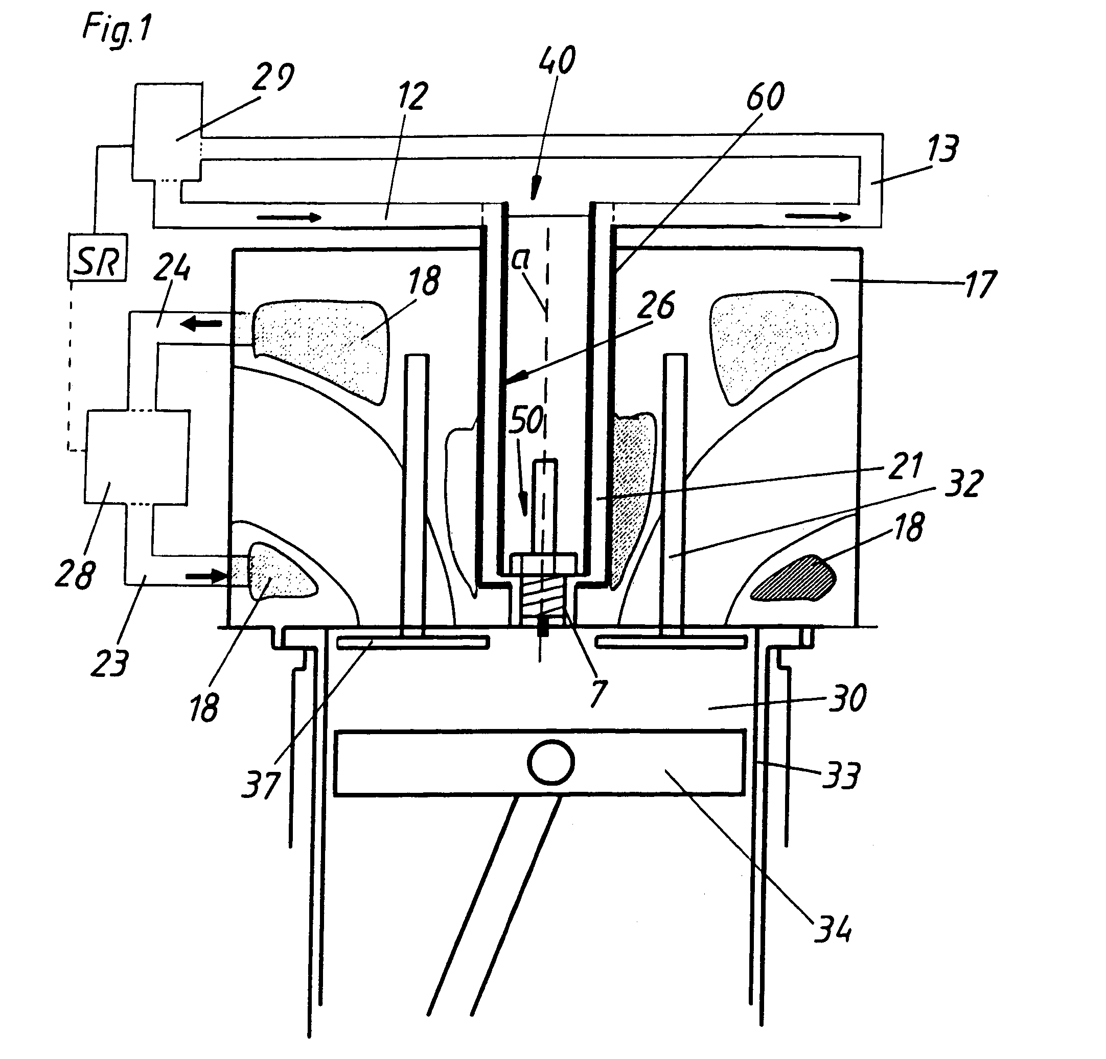
[0034]FIG. 1 shows a diagrammatic cross-section through an arrangement with cylinder head 17, spark plug mounting 60 and spark plug 50 for the situation of use of an engine with direct ignition. In this case, the ignition spark is produced (directly) in the working cylinder of the engine. The engine (of which only a portion is shown) includes in this case inter alia a cylinder 33 with a piston 34 arranged therein and a combustion chamber 30 of an internal combustion engine. An ignitable fuel-air mixture can be introduced into the combustion chamber 30 by way of an inlet valve 32 and can be ignited by the spark plug 50. After combustion, the exhaust gases are carried away by way of the exhaust valve 37. The spark plug 50 and the spark plug mounting 60 together form the internal combustion engine ignition device 40 which is or can be screwed / clamped in the cylinder head 17. Cylinder head cooling cavities 18 (engine cooling water chambers) are shown in section in the cylinder head 17. ...


PUM


Abstract

The invention relates to an arrangement including an internal combustion engine ignition device having a spark plug and a spark plug seat (in which the spark plug can be fastened in a fastening zone), and a cylinder head in which the spark plug is or can be mounted via the spark plug seat. The cylinder head has a cylinder head cooling cavity. The spark plug seat includes a temperature control medium chamber which is separate from the cylinder head cooling cavity and has a cooling medium feed line and a cooling medium discharge line. The temperature control medium chamber and the cylinder head cooling cavity are connected to separate medium temperature control devices and form separate medium systems.

Description

[0001]This application is a Continuation of International Application No. PCT / AT2010 / 000348, filed Sep. 23, 2010, the entire disclosure of which is incorporated herein by reference.BACKGROUND OF THE INVENTION[0002]The invention concerns an arrangement including an internal combustion engine ignition device having a spark plug and a spark plug mounting in which the spark plug can be fastened in a fastening region, and a cylinder head in which the spark plug is or can be mounted by way of the spark plug mounting. The cylinder head has a cylinder head cooling cavity, and the spark plug mounting has a temperature control medium chamber which is separate from the cylinder head cooling cavity and has a medium feed conduit and a medium discharge conduit. The invention further concerns an internal combustion engine ignition device including a spark plug, a spark plug mounting which receives the spark plug and which can be fitted in a cylinder head of an internal combustion engine, as well a...

Claims


Application Information

Patent Timeline
Patent Type & Authority Patents(United States)
IPC IPC(8): F01P3/16
CPCF01P3/16F02F1/242F02P13/00F02P23/04
Inventor GRUBER, FRIEDRICHKRAUS, MARKUS
Owner GE JENBACHER
Why Eureka
Try Eureka