
Cyclone with improved separation of gas from gas laden liquid streams also at reduced flow volumes

a technology of gas-laden liquid and cyclone, which is applied in the direction of reversed direction vortex, foam dispersion/prevention, dispersed particle filtration, etc., can solve the problems of affecting the operation of the cyclon

Inactive Publication Date: 2013-02-05
METABO PAPER SWEDEN
View PDF12 Cites 9 Cited by
  • Summary
  • Abstract
  • Description
  • Claims
  • Application Information

AI Technical Summary

Benefits of technology

The patent describes a new cyclone design that solves problems associated with foam and flow control during operation. The cyclone allows for flexible adjustment of inlet arrangements to optimize outflow rates and avoid the appearance of foam. It also has a final separation of liquid and gas phases and includes special arrangements such as a deflector screen and anti-swirl plate to ensure efficient separation. Overall, the patent provides a solution to design issues and improves the performance of cyclones in various applications.

Problems solved by technology

Furthermore, cyclones known today are in most cases constructed in such a manner that they cannot be adapted to different operating conditions, at least not without a considerable effort, as a result of which they often, in the event of a change in the production process, come to be used in operating conditions which are not optimum.
In the case of liquids with a tendency to foam such a solution proves to have undesirable disadvantages, since the throttling gives rise to a change in the flow pattern and causes a pressure drop which in turn, because of the vapour formation etc., leads to an uneven flow pattern in connection with the outflow inside the cyclone and is thus a cause of foam formation.
Foam formation is very disadvantageous since it disturbs the flow conditions inside the cyclone and thus counteracts optimum operating conditions.
However, replacement of the insertion pipes in the inlet is an operation which calls for interrupted operation of the cyclone.
This would result in an increase in steam consumption and increase of costs.
Any decrease in steam production from the cyclone calls for usage of expensive fresh steam that could be used for other purposes.

Method used


Image

  • Cyclone with improved separation of gas from gas laden liquid streams also at reduced flow volumes
  • Cyclone with improved separation of gas from gas laden liquid streams also at reduced flow volumes
  • Cyclone with improved separation of gas from gas laden liquid streams also at reduced flow volumes

Examples


example of implementation

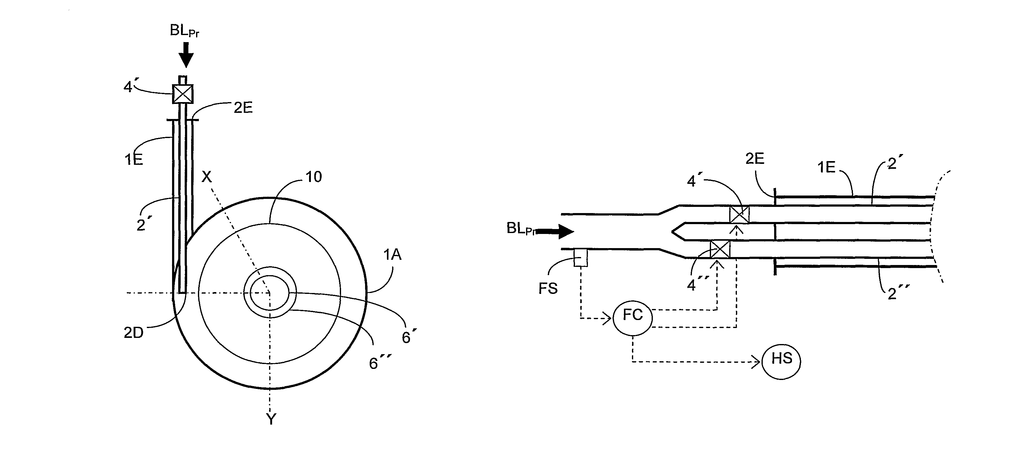
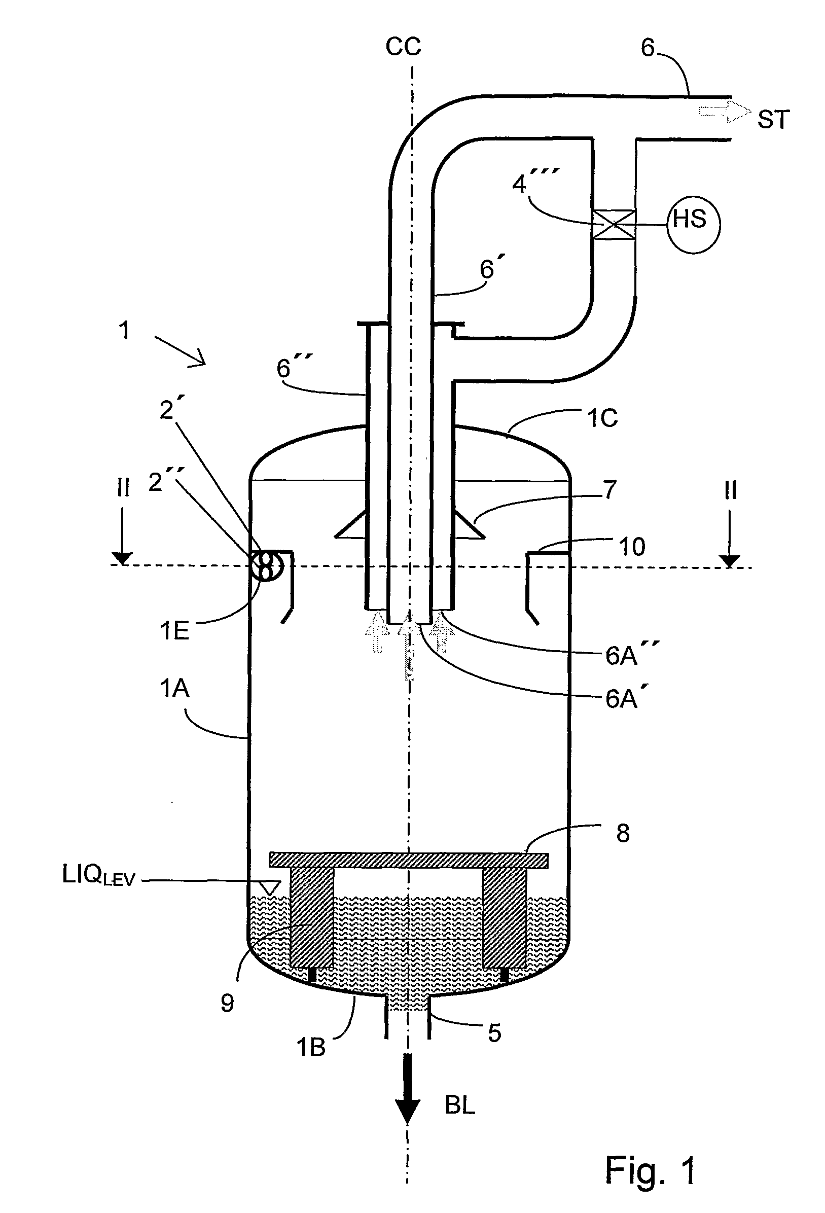
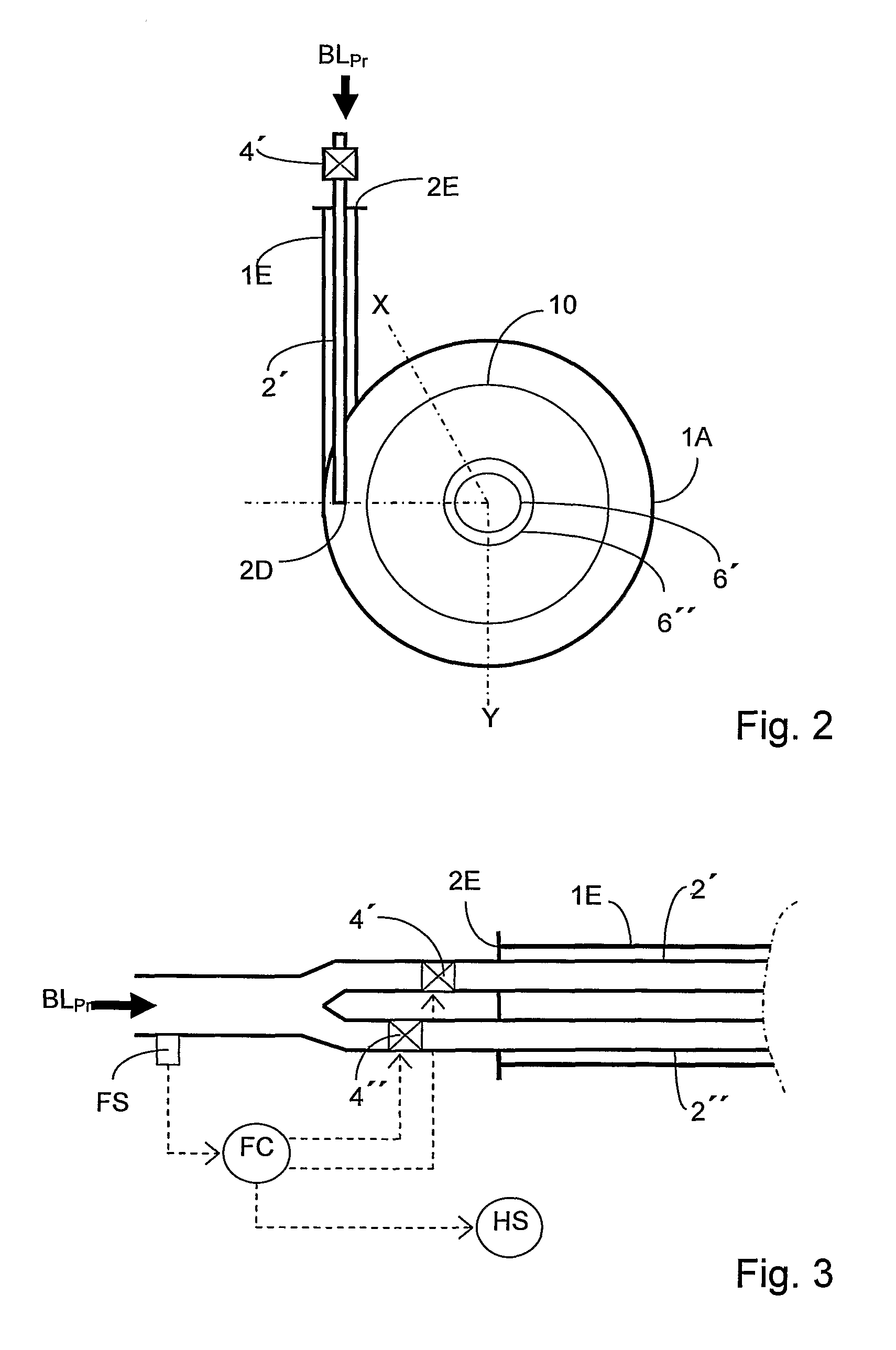
[0038]In a typical flash cyclone for black liquor received from a continuous digester with an output of 900 tonnes / day, is the internal diameter of the cyclone corresponding to 2.5 m and the effective height of about 6 m. The diameter of each single insertion pipe is 140 mm. With a gas laden liquid stream having a pressure which corresponds to 4-5 bar, and a temperature of 152-159° C., an inlet rate corresponding to approximately 40 m / sec is obtained if the pressure in the flash tank is kept at 2.5 bar (g). This is a typical flash tank pressure in a first flash tank in a system with 3 flash tanks in series.

[0039]An inlet rate of 40 m / s is also obtained in a cyclone with single insertion pipe having a single insertion pipe with a diameter of 200 mm at these conditions.

[0040]In order to achieve effective utilisation of the centrifugal force in order to “break up foam” in cyclones of these dimensions (diameter greater than 1 meter), the inlet rate should exceed 30 m / s, which is the min...


PUM

PropertyMeasurementUnit
lengthaaaaaaaaaa
lengthaaaaaaaaaa
lengthaaaaaaaaaa

Abstract

The cyclone is for separating gas from a gas laden liquid stream by pressure reduction of the liquid stream. The cyclone has a cylindrical casing, having a tangentially directed inlet arrangement for the gas laden liquid stream, a lower outlet line for liquid and an upper outlet line for vapor and gas. The inlet arrangement is connected to a common supply source (BLPR), and has at least two insertion pipes. The flow in at least one of these insertion pipes is controlled by at least one valve that depends upon an order of flow from the common supply source to maintain a flow velocity above a critical value.

Description

PRIOR APPLICATION[0001]This application is a U.S. national phase application that claims priority from International Application No. PCT / SE2008 / 000450, filed 14 Jul. 2008.FIELD OF THE INVENTION[0002]The following invention relates to a cyclone, mainly for separating gas / vapour from a pressurised gas laden liquid stream, which separation is obtained by pressure reduction of the gas laden liquid stream. The gas laden liquid stream is preferably pressurised spent cooking liquid obtained from a digester used in pulp production. The cyclone comprises a cylindrical casing, an tangential inlet arrangement for the pressurised gas laden liquid stream, and in opposite ends of the cylindrical casing an outlet line for liquid and an outlet line for vapour and / or gas. Said inlet arrangement being connected to a supply line with at least one valve. The invention relates to a cyclone of the abovementioned type which is cost-effective and which can in a flexible manner be controlled during operatio...

Claims


Application Information

Patent Timeline
Patent Type & Authority Patents(United States)
IPC IPC(8): B01D19/00
CPCB01D19/0026B01D19/0036B01D19/0063B04C5/04B04C11/00B04C5/13
Inventor OLSSON, KRISTER
Owner METABO PAPER SWEDEN
Learn More