Liquid crystal spraying apparatus with ultrasonic converter within nozzle and method for manufacturing of liquid crystal display device using the same

a technology of ultrasonic converter and liquid crystal spraying apparatus, which is applied in non-linear optics, instruments, optics, etc., can solve the problems of increasing fabrication costs, long injection time, and reducing productivity (or yield). , to achieve the effect of minimizing defective unevenness

Active Publication Date: 2013-02-05
LG DISPLAY CO LTD
View PDF17 Cites 2 Cited by
  • Summary
  • Abstract
  • Description
  • Claims
  • Application Information

AI Technical Summary

Benefits of technology

[0022]An advantage of the present invention is to provide a liquid crystal spraying apparatus that can minimize defective unevenness generated during a liquid crystal injection process by directly spraying liquid crystal on a glass substrate.
[0023]Additional advantages and features of the invention will be set forth in part in the description which follows and in part will become apparent to those having ordinary skill in the art upon examination of the following or may be learned from practice of the invention. These and other advantages of the invention may be realized and attained by the structure particularly pointed out in the written description and claims hereof as well as the appended drawings.
[0024]To achieve these and other advantages and in accordance with the purpose of the invention, as embodied and broadly described herein, a liquid crystal spraying apparatus includes a liquid crystal vessel for storing liquid crystal; a liquid crystal nozzle for spraying the stored liquid crystal in a form of fine particles; a liquid crystal supplier for supplying the stored liquid crystal to the liquid crystal nozzle; a gas supplier for supplying a gas to the liquid crystal nozzle; and a gas tank for supplying the gas to the gas supplier.
[0025]In another aspect of the present invention, a liquid crystal spraying apparatus includes a liquid crystal vessel for storing liquid crystal; a liquid crystal nozzle for spraying the stored liquid crystal in a form of fine particles; a liquid crystal supplier for supplying the stored liquid crystal to the liquid crystal nozzle; a ultrasonic converter for converting the supplied liquid crystal into fine particles; a power terminal connected to the ultrasonic converter; and a controller for applying a control signal to the power terminal.
[0026]In yet another aspect of the present invention, a method for fabricating a liquid crystal display (LCD) device includes providing a first substrate and a second substrate; spraying liquid crystal on the first substrate using a sprayer that includes a liquid crystal vessel and a nozzle, wherein the nozzle includes a means to convert the liquid crystal received from the liquid crystal vessel into a plurality of fine particles of the liquid crystal; and attaching the first and second substrates to each other.

Problems solved by technology

First, the process time for injecting liquid crystal 14 into the liquid crystal panel 11 is long. In general, because a cell gap between the array substrate and the color filter substrate in a liquid crystal panel is very small (about several μm), a very small amount of liquid crystal is injected into the liquid crystal panel per unit time. For example, about 8 hours are required to complete the injection of liquid crystal into a 15-inch liquid crystal panel. The long injection time decreases productivity (or yield).
Second, a large portion of the liquid crystal 14 used for the liquid crystal injection process is discarded. That is, only a very small amount of the liquid crystal 14 in the vessel 12 is actually injected into the liquid crystal panel 11. Because the liquid crystal 14 can be degraded by the impurities in the injection apparatus and the gases used as well as by the impurities generated when the liquid crystal 14 comes into contact with the liquid crystal panel 11, the remaining liquid crystal 14 in the vessel 12 after dipping a single liquid crystal panel 11 should be discarded and may not be used for other liquid crystal panels. This increases fabrication costs.

Method used


Image

  • Liquid crystal spraying apparatus with ultrasonic converter within nozzle and method for manufacturing of liquid crystal display device using the same
  • Liquid crystal spraying apparatus with ultrasonic converter within nozzle and method for manufacturing of liquid crystal display device using the same
  • Liquid crystal spraying apparatus with ultrasonic converter within nozzle and method for manufacturing of liquid crystal display device using the same

Examples


first embodiment

[0049]FIG. 4 is a perspective view of a liquid crystal spraying apparatus according to the present invention.

[0050]Referring to FIG. 4, the liquid crystal spraying apparatus 120 includes a liquid crystal vessel 122 is received in a case 123. The liquid crystal vessel 122 is made of polyethylene and filled with liquid crystal 107. Polyethylene is generally used as a material for the liquid crystal vessel 122 because it has a favorable plasticity and does not react with the liquid crystal 107. The case 123 is made of stainless steel.

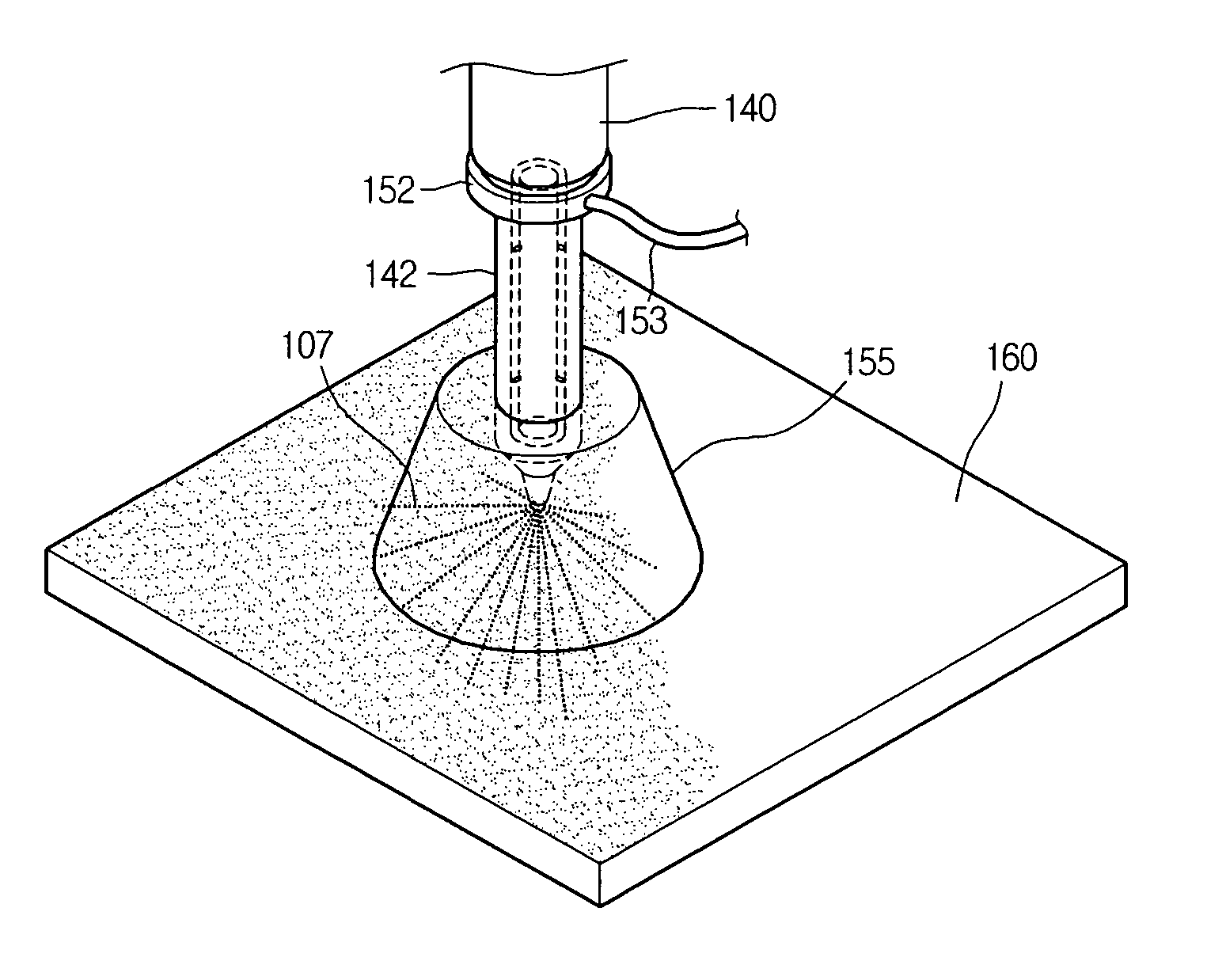
[0051]A liquid crystal supplier 140 is disposed below the liquid crystal vessel 122 and they are connected to each other via a connection tube 126. A liquid crystal nozzle 142 for spraying the liquid crystal 107 is connected to the liquid crystal supplier 140. A gas supplier 152 for spraying the liquid crystal in the form of fine particles is connected to the connection region between the liquid crystal supplier 140 and the liquid crystal nozzle 142. The g...

second embodiment

[0063]FIG. 7 is a view illustrating a liquid crystal spraying apparatus according to the present invention.

[0064]Referring to FIG. 7, the liquid crystal spraying apparatus 220 includes a liquid crystal vessel 222 for storing liquid crystal 207 that is received in a case 223 and connected to a liquid crystal supplier 240 via a connection tube 226. The liquid crystal supplier 240 is directly connected to a liquid crystal nozzle 242 to spray the liquid crystal 207 through the liquid crystal nozzle 242 by a predetermined pressure.

[0065]A ultrasonic converter 252 for converting the liquid crystal 207 into fine particles, and power terminals 251 connected to the ultrasonic converter 252 are installed in the liquid crystal nozzle 242. A controller 250 is connected to the power terminals 251 through cables 253 to apply a predetermined control signal to the power terminals 251. The controller 250, the power terminals 251, the ultrasonic converter 252, and the cables 253 may constitute a ultr...


PUM

PropertyMeasurementUnit
sizeaaaaaaaaaa
pressureaaaaaaaaaa
vibration frequencyaaaaaaaaaa

Abstract

A liquid crystal spraying apparatus is provided. In the apparatus, a liquid crystal vessel stores liquid crystal. A liquid crystal nozzle sprays the stored liquid crystal in the form of fine particles. A liquid crystal supplier supplies the stored liquid crystal to the liquid crystal nozzle. A gas supplier supplies gas causing the supplied liquid crystal to be sprayed in the form of fine particles. A gas tank supplies the gas to the gas supplier.

Description

[0001]This application claims the benefit of Korean Patent Application Nos. 2004-118377, filed on Dec. 31, 2004, and 2005-72339, filed on Aug. 8, 2005, which is hereby incorporated by reference for all purposes as if fully set forth herein.BACKGROUND OF THE INVENTION[0002]1. Field of the Invention[0003]The present invention relates to a liquid crystal display (LCD) device and a method for fabricating an LCD device, and more particularly, to a liquid crystal spraying apparatus that can uniformly dispense liquid crystal to improve the image quality of the LCD device.[0004]2. Discussion of the Related Art[0005]With the development of various portable electronic devices such as mobile phones, PDAs (personal digital assistant), notebook computers, and the like, the demand for flat panel display devices (that are thin, small and lightweight) has recently increased. Various display devices, such as liquid crystal display (LCD) devices, plasma display panels (PDP), field emission displays (...

Claims


Application Information

Patent Timeline
Patent Type & Authority Patents(United States)
IPC IPC(8): G02F1/1341G02F1/1339
CPCG02F1/1341G02F2001/13415G02F1/13415
Inventor KIM, KANG SUKSONG, TAE JOON
Owner LG DISPLAY CO LTD
Why Eureka
Try Eureka