
System and apparatus for vectoring nozzle exhaust plume from a nozzle

a technology of exhaust plume and system, which is applied in the direction of vessel construction, aircraft navigation control, marine propulsion, etc., can solve the problems of compromising the internal shaping of the nozzle, bleeding high pressure flow, and heavy nozzles

Active Publication Date: 2013-02-12
LOCKHEED MARTIN CORP
View PDF19 Cites 9 Cited by
  • Summary
  • Abstract
  • Description
  • Claims
  • Application Information

AI Technical Summary

Benefits of technology

This approach enables efficient thrust vectoring with reduced weight and complexity, optimizing internal nozzle geometry for peak thrust while maintaining vectoring capability, and reduces the need for engine bleed, thus enhancing overall performance and reducing costs.

Problems solved by technology

However, these nozzles are heavy, complex and expensive.
This results from compromising nozzle internal shaping and bleeding high pressure flow from the engine to supply the fluid injectors.
For example, the desired vectoring capability may require a larger nozzle exit area than that required for peak thrust performance, resulting in nozzle thrust loss.
Also, bleeding a portion of the engine airflow to provide a source for the fluid injectors incurs engine performance penalties.

Method used


Image

  • System and apparatus for vectoring nozzle exhaust plume from a nozzle
  • System and apparatus for vectoring nozzle exhaust plume from a nozzle
  • System and apparatus for vectoring nozzle exhaust plume from a nozzle

Examples


Embodiment Construction

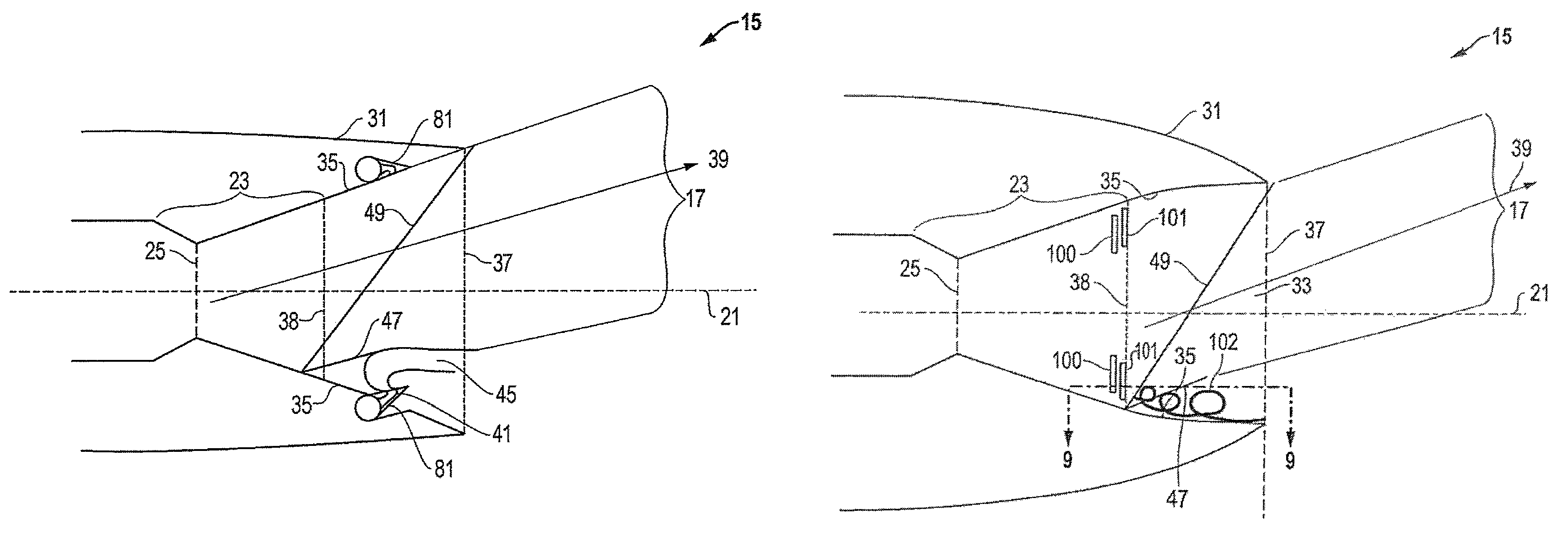
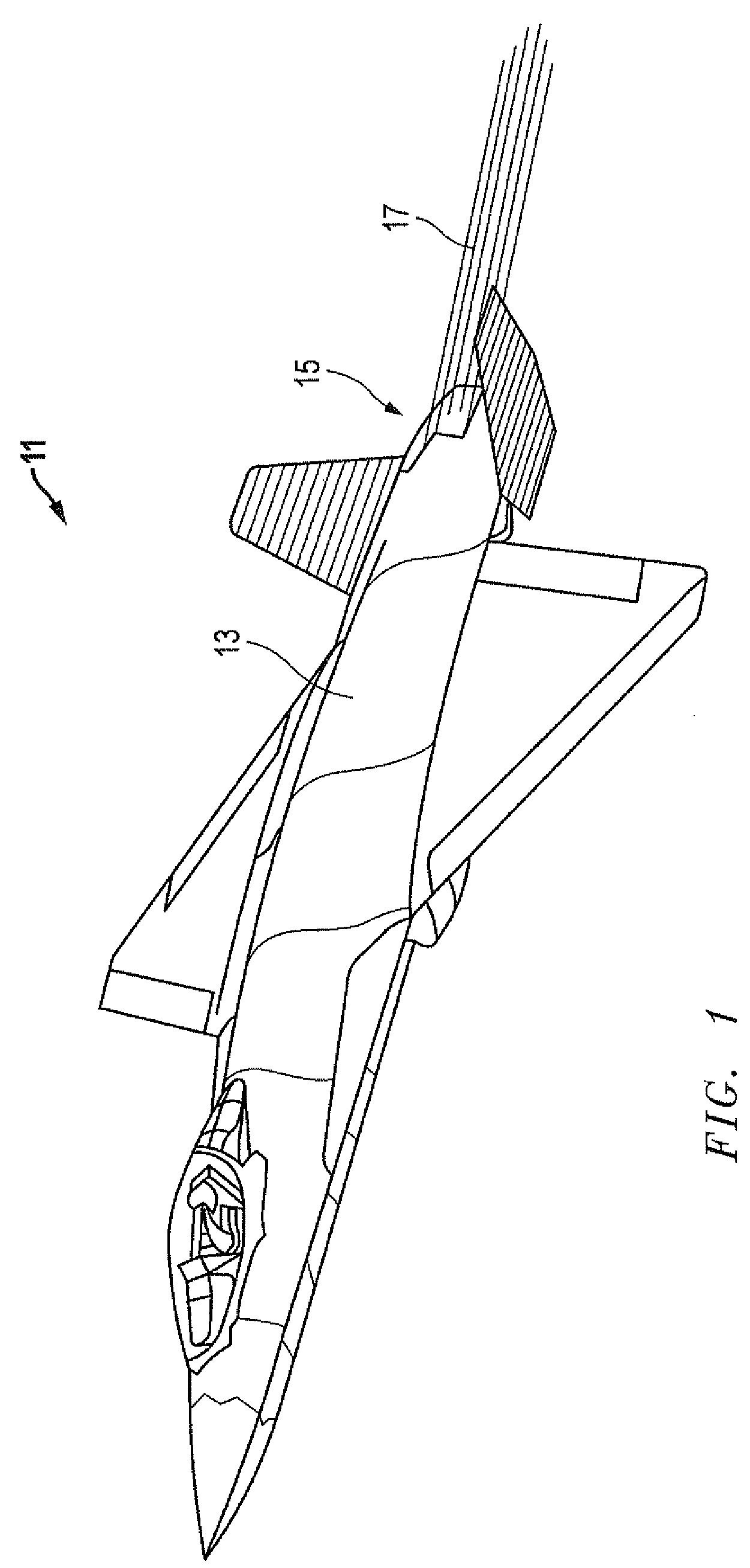
[0020]Referring to FIGS. 1-9, embodiments of a system, method, and apparatus for vectoring nozzles with external actuation relative to the nozzle are disclosed. In one application, the invention is well suited for use with an aircraft, such as aircraft 11 depicted in FIG. 1. Aircraft 11 has a body 13 with an internal propulsion system or engine. Aircraft 11 also has a highly integrated exhaust system 15 located aft of the propulsion system for releasing an exhaust plume 17.

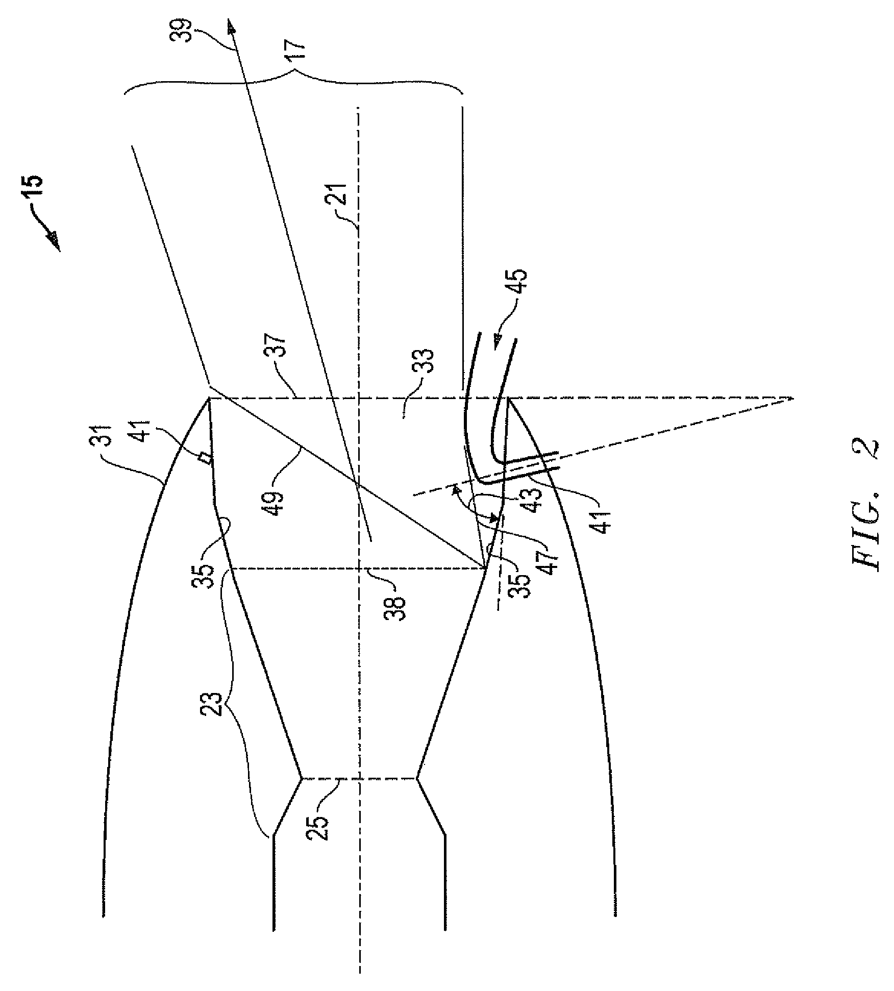
[0021]One embodiment of the highly integrated exhaust system 15 is shown in FIG. 2 and, for reference purposes, includes an exhaust axis 21 that extends in a longitudinal direction. The highly integrated exhaust system 15 has a nozzle 23 with a throat 25. The portion of the nozzle upstream of the throat is referred to as the convergent section, and the portion downstream of the throat is referred to as the divergent section. The shapes of nozzle 23 and throat 25 may vary by application, but are not necessarily cir...


PUM


Abstract

A vectoring nozzle with external actuation generates thrust vectoring by applying mechanical or fluidic actuation, or both, on the nozzle deck, external sidewalls, and / or air vehicle aft body to produce changes in the aft body flowfield and / or exhaust plume. An external mechanical sidewall may be integrated into a nozzle deck or side walls without the need for engine bleed to supply fluid injectors. An external fluidic vectoring system uses injectors or plasma devices located aft of the nozzle exit to vector the exhaust plume with no external moving parts. Elements of both mechanical and fluidic systems may be combined for a given application.

Description

BACKGROUND OF THE INVENTION[0001]1. Technical Field[0002]The present invention relates in general to controlling aircraft exhaust and, in particular, to an improved system, method, and apparatus for vectoring the exhaust plume from a nozzle with external actuation relative to the nozzle.[0003]2. Description of the Related Art[0004]Higher demands for air vehicle performance and affordability directly impact exhaust system requirements. Future exhaust systems must provide a high thrust coefficient, thrust vectoring with quick response, compatibility with engine operation, light weight, and low cost. Mechanical vectoring systems can achieve good thrust and vectoring performance by actuating large surfaces that comprise part of the nozzle. However, these nozzles are heavy, complex and expensive.[0005]Fluidic nozzle vectoring systems are significantly lighter and simpler than mechanical vectoring systems due to the use of integral fluid injectors for thrust vector control. This permits t...

Claims


Application Information

Patent Timeline
Patent Type & Authority Patents(United States)
IPC IPC(8): F02K1/28
CPCF02K1/08F02K1/10F02K1/1207F02K1/28F02K1/30Y02T50/671Y02T50/60
Inventor WELLS, DAVID M.MCCALLUM, BRENT N.GINN, KERRY B.JENKINS, STEWART A.
Owner LOCKHEED MARTIN CORP
Learn More