Hydraulic system for fan pitch change actuation of counter-rotating propellers

a technology of propeller and hydraulic system, which is applied in the direction of rotors, marine propulsion, vessel construction, etc., can solve the problem that the small area provided by the slip rings to transfer the required volume of hydraulic fluid or oil to both rotating frames may be insufficient at a certain pressur

Active Publication Date: 2013-02-12
GENERAL ELECTRIC CO
View PDF23 Cites 17 Cited by
  • Summary
  • Abstract
  • Description
  • Claims
  • Application Information

AI Technical Summary

Benefits of technology

[0015]The forward union stator may be mounted on the forward structural turbine frame and the forward union stator connected to the hydraulic fluid supply by hydraulic fluid forward supply and return lines and the aft union stator may be mounted on the aft structural turbine frame and the aft union stator connected to the hydraulic fluid supply by hydraulic fluid aft supply and return lines. The forward hydraulic rotary union is operable for transferring pressurized hydraulic fluid between the hydraulic fluid forward supply and return lines and aft supply and return rotatable lines respectively and the aft hydraulic rotary union is operable for transferring the pressurized hydraulic fluid between the hydraulic fluid aft supply and return lines and forward supply and return rotatable lines respectively. The forward union rotor is connected to the aft supply and return rotatable lines mounted in the aft rotatable frame and connected to the aft pitch change actuators and the aft union rotor is connected to the forward supply and return rotatable lines mounted in the forward rotatable frame and connected to the forward pitch change actuators.

Problems solved by technology

The small area provided by the slip rings to transfer a required volume of hydraulic fluid or oil to both rotating frames may be insufficient at a certain pressure.

Method used


Image

  • Hydraulic system for fan pitch change actuation of counter-rotating propellers
  • Hydraulic system for fan pitch change actuation of counter-rotating propellers
  • Hydraulic system for fan pitch change actuation of counter-rotating propellers

Examples


Embodiment Construction

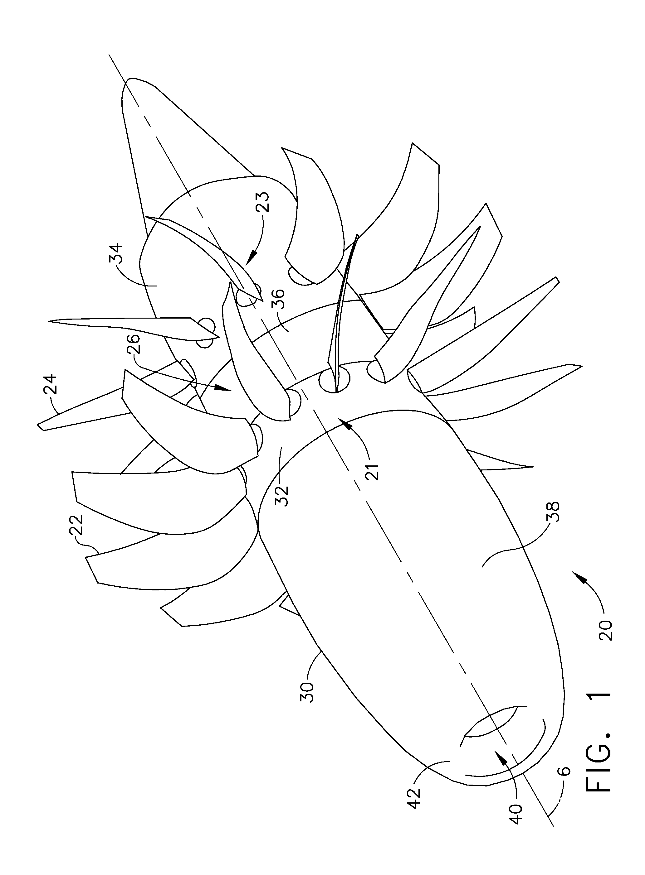
[0031]FIG. 1 illustrates an unducted fan (UDF) or open rotor aircraft gas turbine engine 20 having a centerline axis 6 and axially spaced apart counter-rotatable forward and aft annular rows 21, 23 of forward and aft propellers 22, 24 respectively that are disposed radially outwardly of an outer shroud or nacelle 30. The forward and aft annular rows 21, 23 are illustrated herein as having 12 forward propellers 22 and 10 aft propellers 24 but other numbers of propellers may be used. The nacelle 30 includes a forward fairing 32 which is coupled to and rotatable with the forward propellers 22 and an aft fairing 34 coupled to and rotatable with the aft propeller 24.

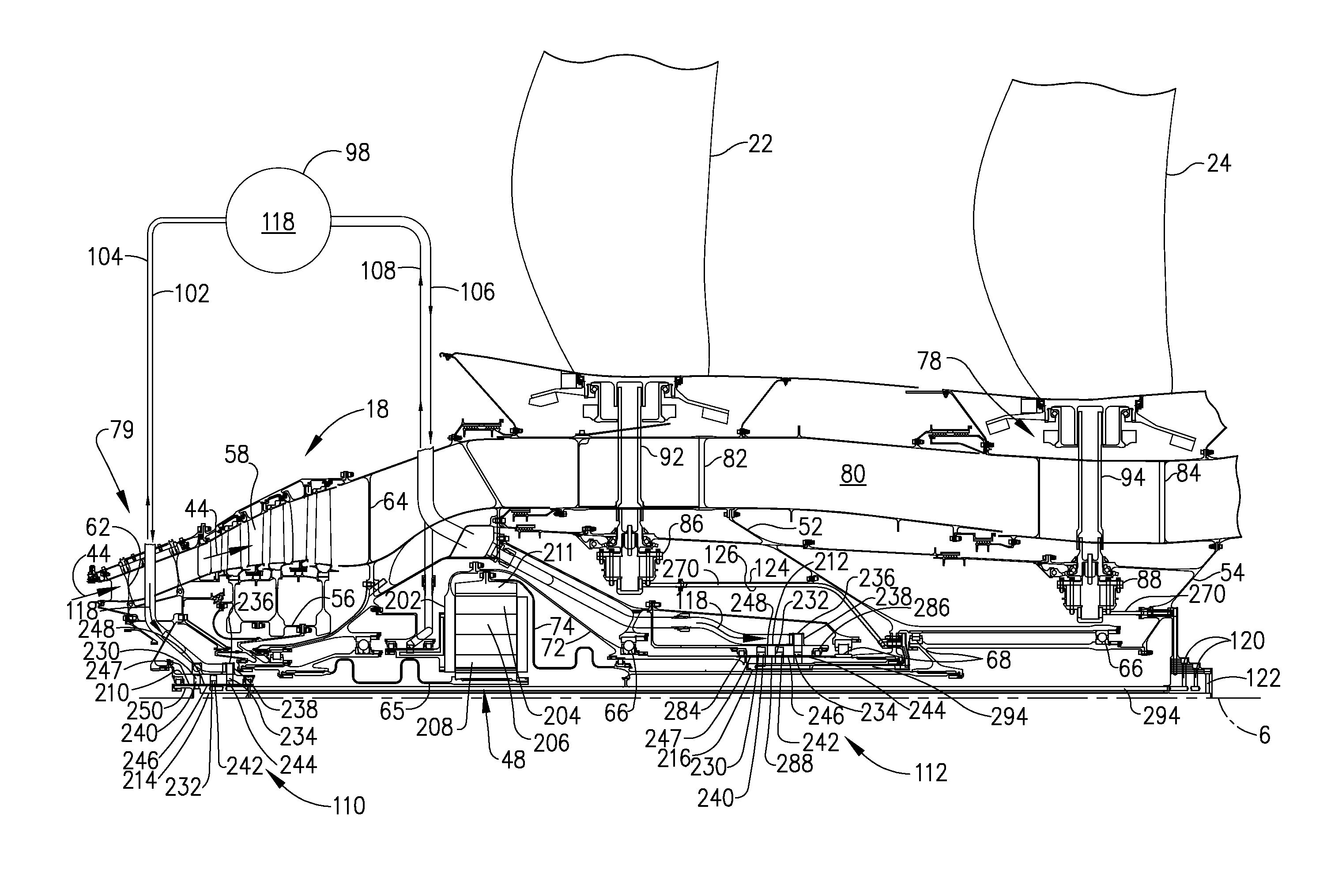
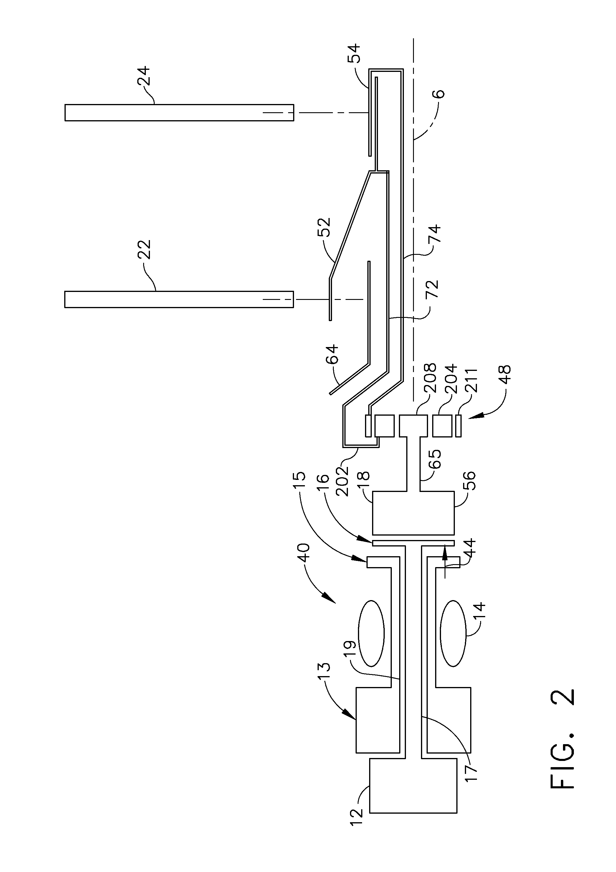
[0032]The nacelle 30 further includes a spacer fairing 36 disposed between the forward and aft fairings 32, 34 and a forward nacelle 38 disposed radially outwardly of and surrounding a gas generator 40 illustrated in FIG. 2. The forward nacelle 38 includes an inlet 42 that directs ambient air to the gas generator 40. The nace...


PUM


Abstract

Spaced apart counter-rotatable forward and aft rows of forward and aft propellers are mounted on forward and aft rotatable frames. Hydraulic rotary forward and aft pitch change actuators on the frames are operable for controlling pitch of the propellers. A hydraulic fluid supply outboard of the frames is connected to forward and aft rotary unions which are operable for transferring hydraulic fluid between forward and aft union stators to forward and aft union rotors mounted within the forward and aft rotary unions. The forward union rotor is operable to transfer the hydraulic fluid from the forward rotary union to the aft pitch change actuators and the aft union rotor is operable to transfer the hydraulic fluid from the aft rotary unions to the forward pitch change actuators. The forward and aft rotatable frames counter-rotatably mounted on a structural frame located forward or aft of the propellers.

Description

BACKGROUND OF THE INVENTION[0001]1. Field of the Invention[0002]The invention relates to pitch change systems for aircraft gas turbine engine counter-rotatable propellers and, more particularly, to hydraulic systems for pitch change actuation of counter-rotatable propellers.[0003]2. Description of Related Art[0004]One type of aircraft gas turbine engine includes a power turbine driving counter-rotatable propeller rotors and the power turbine is powered by a gas generator. A pitch change actuation system including a hydraulic fluid delivery system is used for pitch change actuation of counter-rotatable propellers mounted on the counter-rotatable propeller rotors. The pitch change system includes pitch change actuators mounted in counter-rotatable frames which also support the counter-rotatable propellers and blades.[0005]U.S. Pat. No. 4,621,978 by Alan R. Stuart, which issued Nov. 11, 1986, is entitled “Counterrotating Power Turbine”, and is assigned to the General Electric Company, ...

Claims


Application Information

Patent Timeline
Patent Type & Authority Patents(United States)
IPC IPC(8): F02K3/00
CPCF01D7/00F02C6/206B64D2027/026F05D2220/324F05D2260/74F05D2260/79B64D2027/005Y02T50/60
Inventor GLYNN, CHRISTOPHER CHARLESZATORSKI, DAREK TOMASZYEAGER, DONALD SCOTTDINSMORE, NICHOLAS ROWEMENARD, JEFFREY RAYMONDMILLER, BRANDON WAYNE
Owner GENERAL ELECTRIC CO
Why Eureka
Try Eureka