Peristaltic pump with linear flow control

a technology of linear flow control and pump, which is applied in the field of infusion pump, can solve the problems of unsatisfactory fluctuations in the rate at which fluid is delivered to the patient, and achieve the effect of enhancing the balancing of forces

Active Publication Date: 2013-02-12
EITHAN MEDICAL LTD
View PDF95 Cites 47 Cited by
  • Summary
  • Abstract
  • Description
  • Claims
  • Application Information

AI Technical Summary

Benefits of technology

[0007]In some embodiments, the conduit includes an elastic material, which exerts a first force against the fingers in response to compression of the conduit by the fingers, and the fingers include magnets, and the pump includes a ferromagnetic frame, which exerts a second force on the magnets, opposite to and balancing the first force during the pump cycle. In one embodiment, the pump mechanism includes a camshaft, which is coupled to be driven by the motor and includes multiple cams, each configured to drive a respective finger and having a crescent-shaped design for enhancing the balancing of the forces.

Problems solved by technology

At high fluid delivery rates, this variation may not be clinically significant; but the inventors have discovered that the variation in the output at low flow rates, which are typical in delivery of certain medications, for example, can cause undesirable fluctuations in the rate at which the fluid is delivered to the patient.

Method used


Image

  • Peristaltic pump with linear flow control
  • Peristaltic pump with linear flow control
  • Peristaltic pump with linear flow control

Examples


Embodiment Construction

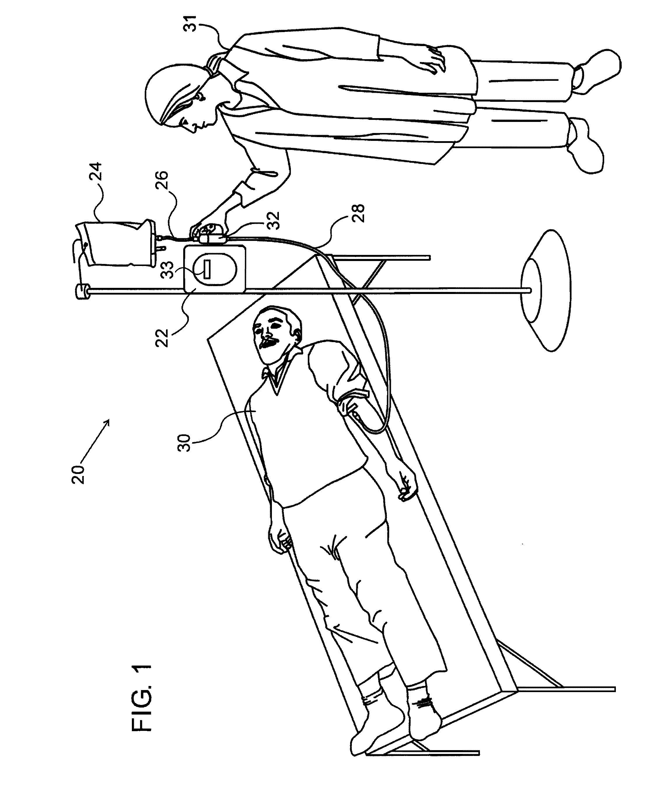
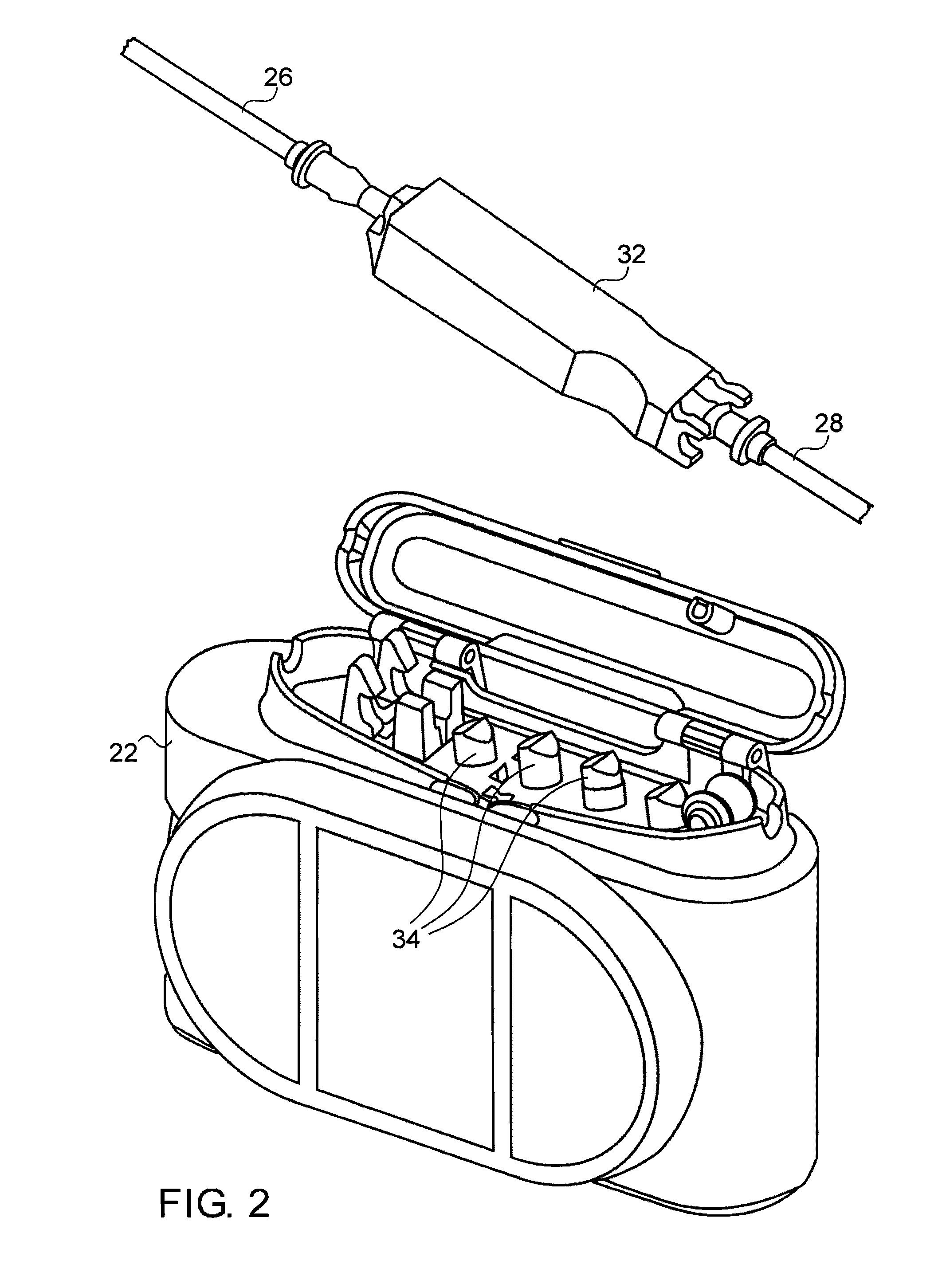
[0021]FIG. 1 is a schematic, pictorial illustration of a medical infusion system 20, in accordance with an embodiment of the present invention. System 20 comprises a peristaltic infusion pump 22, which may pump an infusion fluid from a reservoir 24, through an upstream tube segment 26 (commonly referred to as the “supply line”) and a downstream tube segment 28 (commonly referred to as the “patient line”), into a vein of a patient. This particular type of infusion system is shown here by way of illustration, but the principles of the present invention, as described hereinbelow, may likewise be applied to other types of peristaltic pumps and in substantially any sort of application that uses such pumps, particularly in delivery of drugs. Although the pictured embodiment represents a clinical environment, the devices and methods described herein are also suitable for ambulatory and home use.

[0022]Tube segments 26 and 28 may be connected to a mechanical interface unit 32, which couples ...


PUM


Abstract

A peristaltic pump includes a conduit having a first end for receiving a fluid from a reservoir and a second end for delivering the fluid. A plurality of fingers are disposed at respective locations along a segment of the conduit and are configured to alternately compress and release the conduit at the locations. A cyclical pump mechanism is coupled to move the fingers between respective compressed and released positions in a spatio-temporal pattern so as to drive a predetermined quantity of the fluid through the segment of the conduit in each pump cycle. A motor is coupled to drive the pump mechanism. A controller is coupled to activate and deactivate the motor in alternation during each pump cycle with a duty cycle that varies within the pump cycle.

Description

FIELD OF THE INVENTION[0001]The present invention relates generally to medical devices, and specifically to infusion pumps.BACKGROUND OF THE INVENTION[0002]Various types of medical infusion pumps are known in the art. One common type of infusion pump is a peristaltic pump, in which fluid is made to flow through an elastic tube by external compression of the tube. Typically, a peristaltic mechanism, such as a set of cams or fingers, compresses the tube in a cyclic pattern at a sequence of locations along the length of the tube, so as to cause the fluid to flow through the tube at a desired volumetric rate. Peristaltic infusion pumps are described, for example, in U.S. Pat. Nos. 5,290,158, 5,395,320, and 5,807,322, as well as in U.S. Patent Application Publications 2007 / 0269324, 2009 / 0221964 and 2009 / 0240201, and in PCT International Publication WO 2008 / 059496. The disclosures of all of these cited patents and publications are incorporated herein by reference.SUMMARY OF THE INVENTION[...

Claims


Application Information

Patent Timeline
Patent Type & Authority Patents(United States)
IPC IPC(8): F04B43/12
CPCA61M5/14228F04B43/12F04B43/082F04B49/065F04B35/04F04B43/1253F04B49/02A61M2205/3365A61M2205/50F04B43/09F04B49/06F04B49/20
Inventor ROTEM, SHACHAROFFER, MEGED
Owner EITHAN MEDICAL LTD
Why Eureka
Try Eureka