
Roll assembly for a fiber-web machine and method of attenuating vibration of a fiber-web machine roll

a fiber-web machine and roll technology, applied in the field of roll, can solve the problems of increasing the difficulty of adjusting the vibration of objects, so as to improve the level of technology and improve the effect of adjusting the vibration of rolls

Inactive Publication Date: 2013-02-12
VALMET TECH INC
View PDF21 Cites 2 Cited by
  • Summary
  • Abstract
  • Description
  • Claims
  • Application Information

AI Technical Summary

Benefits of technology

[0011]The particular purpose of the present invention is to raise the level of technology from prior art by providing such a roll assembly for a fiber-web machine, by which the roll vibrations can be affected more efficiently than before. A special purpose of the invention is to provide a method of attenuating the vibration of slender rolls.
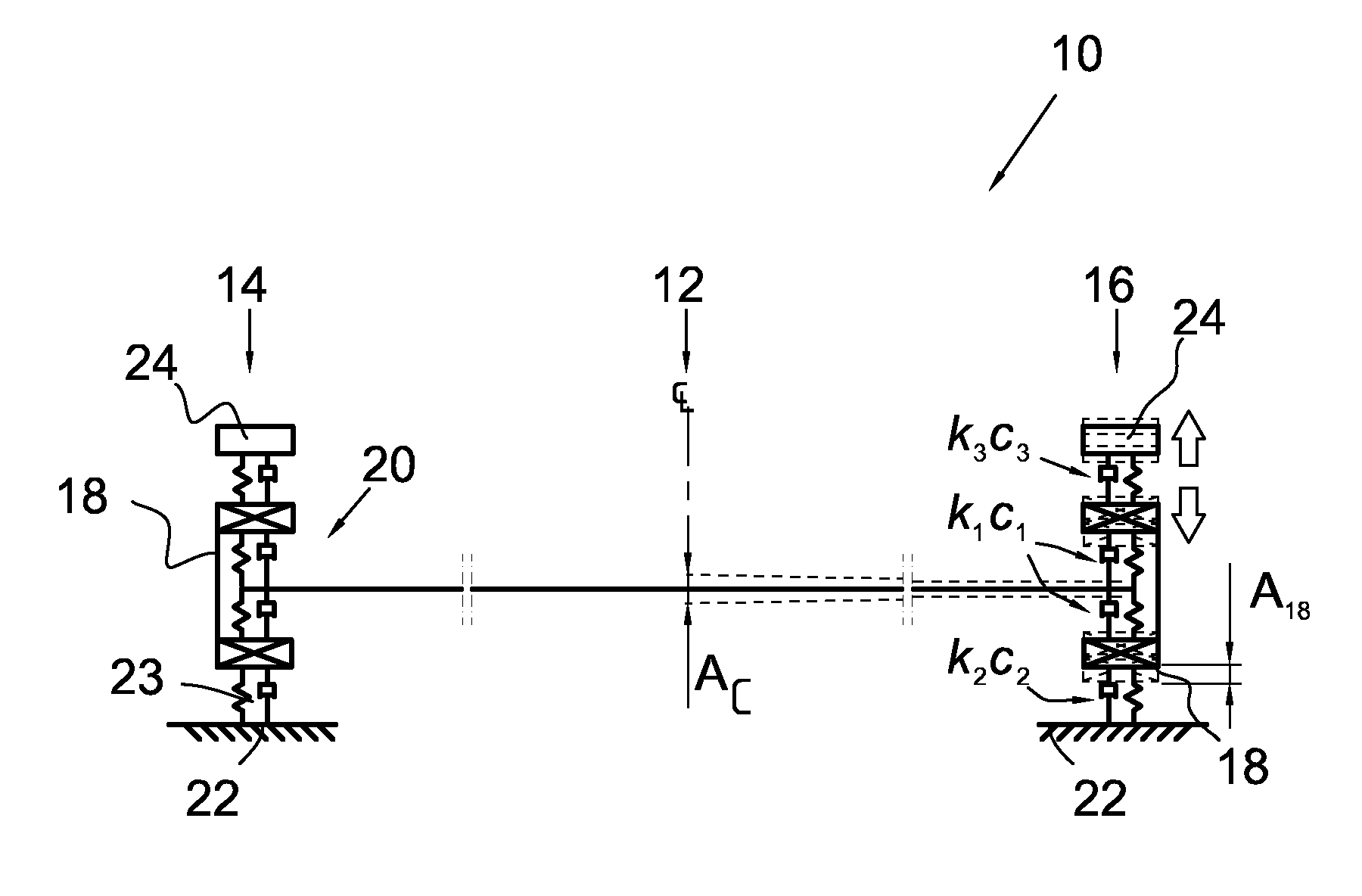
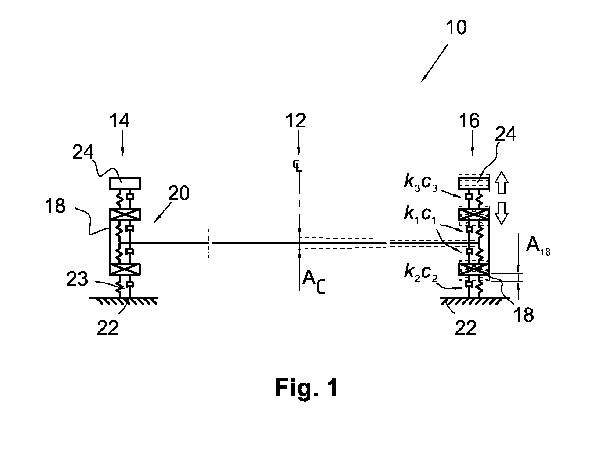
[0015]Such a flexible and attenuating attachment of the bearing housing creates prerequisites for efficient operation of the mass absorber. In addition, the overall effect is improved even if the stiffness of the bearing housing attachment is decreased. In other words, by bringing the bearing housing to vibrate with a larger vibratory motion range by arranging its attachment more flexible than before, a stronger excitation is created for the mass absorber and thereby more efficient overall operation is provided.
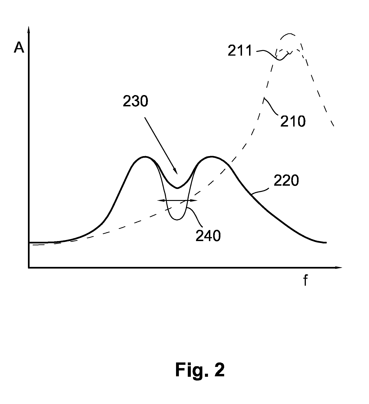
[0021]In the method, due to the flexible attachment of the bearing housing of the roll, the relative movement of the bearing housing with respect to the roll body is increased at the lowest bending eigenfrequency, whereby the efficiency of the mass absorber is improved. In this context, the efficiency of the mass absorber is to be understood as the ratio between the reduction of the maximum value of the amplitude of the frequency response function of the lowest bending eigenfrequency and the mass of the mass absorber, measured at the roll center.
[0022]By the method of this kind, the vibrations of a rotating roll can be damped very efficiently. The advantages of the invention are most obvious in case of a slender roll. In this context, a slender roll refers to such a roll, the shell length of which is at least seven times the diameter of the roll shell.
[0027]According to one embodiment, the operation of the mass absorber is tuned during the operation of the fiber-web machine. Then, it is advantageous to set the natural frequency of the mass absorber itself to follow a desired excitation frequency. Especially when applying the invention to a roll of a reel-up of a slitter-winder, the natural frequency of the mass absorber is set to follow the excitation frequency of the web roll / rolls to be wound.

Problems solved by technology

Along with the increasing widths and higher speeds of fiber-web machines, the vibration of rolls is becoming an ever-increasing problem.
Especially, the winding drums and drums of slitter-winders used for web finishing are challenging objects in terms of vibration, since the winding of customer reels of different sizes and possibly containing various kinds of flaws will easily get disturbed due to excessive vibration.
Vibration is a problem particularly in two-drum or belt-type winders.
A vibration problem occurring with drum winders arises when the harmonics of the rotational speed of a paper roll produced on drums excites the natural frequencies of the drums.
The same type of a vibration problem occurs also with the reeling drums of reel-ups.
The resonance vibrations during the operation of a machine or a device are often caused by insufficient damping, i.e. inadequate dynamic stiffness at the resonance frequency.
However, this kind of a solution is not always capable of providing sufficient attenuation of vibration.
This weakens the efficiency of the damping solution according to F1 patent 118482 especially for slender rolls.

Method used


Image

  • Roll assembly for a fiber-web machine and method of attenuating vibration of a fiber-web machine roll
  • Roll assembly for a fiber-web machine and method of attenuating vibration of a fiber-web machine roll
  • Roll assembly for a fiber-web machine and method of attenuating vibration of a fiber-web machine roll

Examples


Embodiment Construction

[0034]FIG. 1 shows schematically a roll assembly 10 for a fiber-web machine according to one embodiment of the invention. In the figure, the roll of the roll assembly is cut in the longitudinal direction (in the cross-direction of the fiber-web machine) at two points, whereby the central area 12 of the roll and the first and second end 14, 16 thereof are shown herein. Further, the vibration of the roll assembly during operation is illustrated on the right side in the figure. The roll is a so-called slender roll, the length of which is at least seven times the diameter of the roll shell. The roll is rotatably attached at its ends by means of bearing assemblies 20. The roll is attached on the bearing assembly 20 in the bearing housings 18 located at its both ends.

[0035]The flexibility of the bearing assembly is indicated by the spring constant k1 and the attenuation by the attenuation constant c1. Here, the attenuation is described by way of example as viscous damping, but the attenua...


PUM

PropertyMeasurementUnit
lengthaaaaaaaaaa
diameteraaaaaaaaaa
natural frequencyaaaaaaaaaa

Abstract

A roll assembly (10) for a fiber-web machine has at least at one end thereof, with a bearing assembly (20) with a bearing housing, which bearing housing (18) has a flexible and attenuating attachment arrangement by means of which the roll can be attached in a flexible and attenuating manner on the frame or foundation (22) of the fiber-web machine. A mass absorber (24) is arranged in conjunction with the bearing housing, whereby the damping of the vibration of the roll assembly is arranged by the cooperation of the bearing housing that is attached in a flexible and attenuating manner and the mass absorber (24) in conjunction therewith. The invention also relates to a method of attenuating the vibration of a roll of a fiber-web machine.

Description

CROSS REFERENCES TO RELATED APPLICATIONS[0001]This application is a U.S. national stage application of International Application No. PCT / FI2010 / 050122, filed Feb. 23, 2010, the disclosure of which is incorporated by reference herein, and claims priority on Finnish App. No. 20095277, filed Mar. 18, 2009.STATEMENT AS TO RIGHTS TO INVENTIONS MADE UNDER FEDERALLY SPONSORED RESEARCH AND DEVELOPMENT[0002]Not applicableBACKGROUND OF THE INVENTION[0003]The present invention relates to a roll assembly for a fiber-web having at least at one end thereof a bearing assembly with a bearing housing, which bearing housing comprises a flexible and attenuating attachment arrangement, by means of which the roll can be attached in a flexible and attenuating manner on the frame or foundation of the fiber-web machine. The invention also relates to a method of attenuating the vibration of a fiber-web machine roll, in which method the roll is rotatably attached at its ends on a bearing assembly in bearing ...

Claims


Application Information

Patent Timeline
Patent Type & Authority Patents(United States)
IPC IPC(8): D21F11/00
CPCB65H18/00B65H2601/524Y10T29/49826B65H2301/41485B65H2301/414866B65H2601/5242D21G1/008F16C13/00F16F15/02
Inventor JORKAMA, MARKO
Owner VALMET TECH INC
Learn More