
Panel, method of joining panels and method manufacturing panels

a technology of joining panels and manufacturing methods, applied in the field of panels, can solve the problems of increased production costs, increased production costs, and increased production costs of tongue elements, and achieve the effects of improving vertical force transmission, simple and cost-effective production, and safe protection from overstretching

Active Publication Date: 2013-02-19
VÄLINGE INNOVATION AB
View PDF33 Cites 48 Cited by
  • Summary
  • Abstract
  • Description
  • Claims
  • Application Information

AI Technical Summary

Benefits of technology

The solution provides a cost-effective, stable, and reliable locking mechanism suitable for thin panels, reducing the risk of misinstallation and enhancing durability under normal stress conditions.

Problems solved by technology

Special injection molding tools are required for the manufacture of this tongue element, so that the production is relatively expensive.
Furthermore, a high-quality plastic has to be used to provide adequate strength values, which makes the tongue element even more expensive.
The fact that the locking element is embodied as a separate component results in additional expenses.
For technological reasons the production of the locking element takes place in a separate location from the panels, so that integration into the continuous production process, in particular for floor panels, is hardly possible.
Because of the different materials, wood material on the one hand and plastic on the other hand, it is complex and cost-intensive to match the manufacturing tolerances from two separate production processes.
Since the locking in the vertical direction would be ineffective if the locking element were missing, this element must further be secured from falling out of the groove introduced into the side edge during the further production process and during transport.
This securing is also complex.
Furthermore, it cannot be ruled out that the self-installers make a mistake when placing the tongue element, which means that precise locking is not possible and the bond separates over time.
This is then wrongly attributed by the consumer to the quality supplied by the manufacturer.
However, this inevitably means that only low, vertically aligned forces can be absorbed, so that production must be carried out with extremely low tolerances in order to ensure that the connection does not spring open with normal stress in the case of even slight irregularities in the floor and / or soft subfloors.
However, this locking is not suitable for thinner panels with a board thickness of approximately 4 mm to 8 mm.

Method used


Image

  • Panel, method of joining panels and method manufacturing panels
  • Panel, method of joining panels and method manufacturing panels
  • Panel, method of joining panels and method manufacturing panels

Examples


Embodiment Construction

[0031]The particulars shown herein are by way of example and for purposes of illustrative discussion of the embodiments of the present invention only and are presented in the cause of providing what is believed to be the most useful and readily understood description of the principles and conceptual aspects of the present invention. In this regard, no attempt is made to show structural details of the present invention in more detail than is necessary for the fundamental understanding of the present invention, the description taken with the drawings making apparent to those skilled in the art how the several forms of the present invention may be embodied in practice.

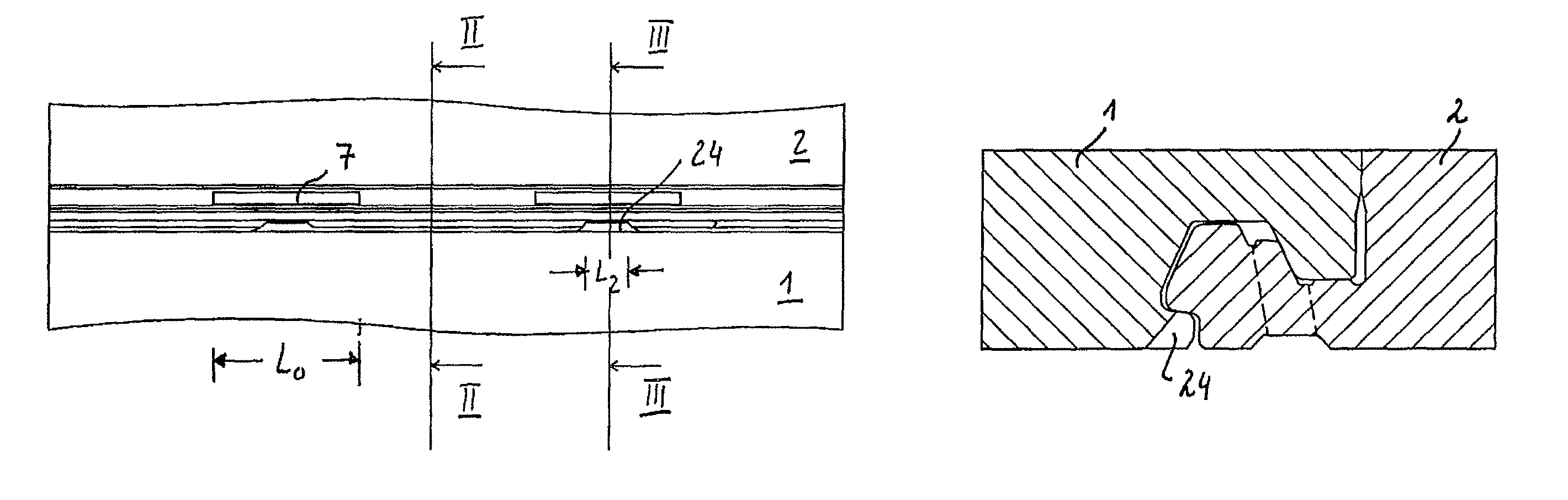
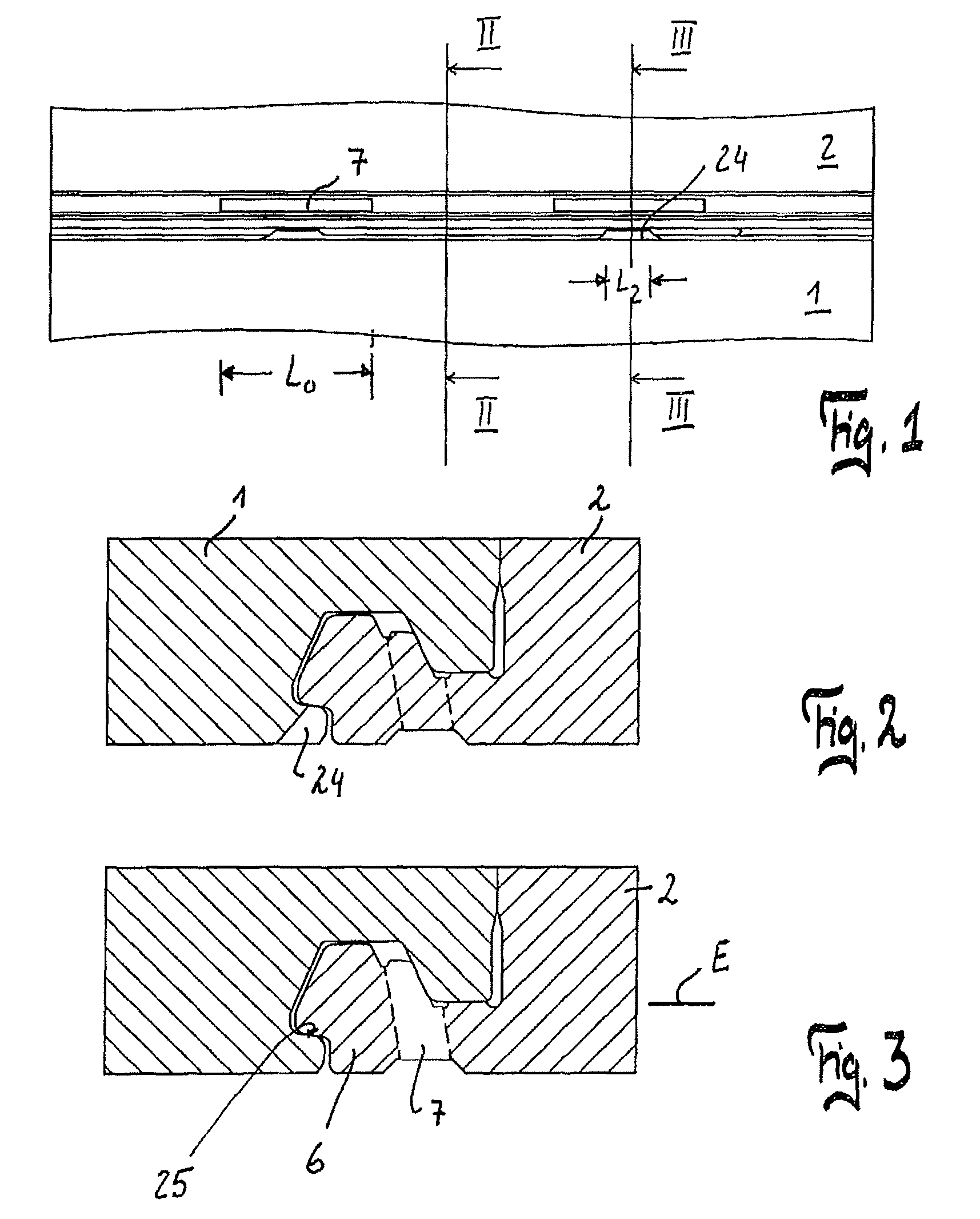
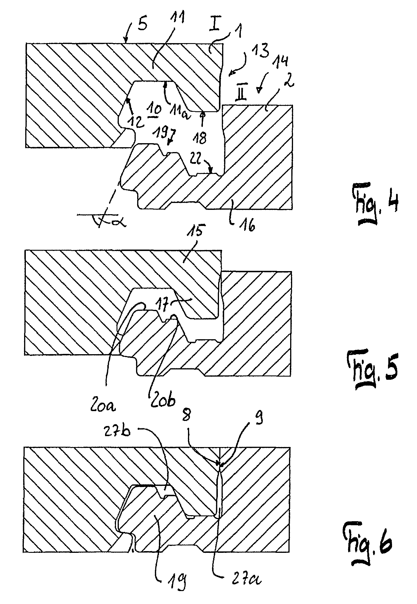
[0032]The panel of the present invention has a top and an underside and two opposite side edges, which have profiles that correspond to each other such that two identically configured panels can be connected and locked to one another in the horizontal and vertical directions by an essentially vertical joining movement. Th...


PUM


Abstract

A panel has a core of wood material or a wood material / plastic mixture, a top and an underside, and two opposite side edges, which have profiles that correspond to each other such that two identically configured panels can be connected and locked to one another in the horizontal (H) and vertical (V) directions by an essentially vertical joining movement. The locking in the horizontal direction (H) can be brought about by a hook connection with an upper locking section having a hook element and a lower locking section having a hook element. The locking in the vertical direction (V) can be brought about by at least one tongue element that is formed from the core in one piece and can be moved in the horizontal direction (H). The at least one tongue element provided on the lower locking section is free with respect to the core in the direction of the opposite side edge by means of an essentially vertical slot and during the joining movement snaps in behind a locking edge extending essentially in the horizontal direction (H), which locking edge is embodied on a locking projection. The tongue element is connected to the core on at least one of its two ends in the direction of its side edge (II), and the width (B1, B2) of the locking edge is different in size over the length (L) of the opposite side edge (I).

Description

CROSS-REFERENCE TO RELATED APPLICATIONS[0001]The present application claims priority under 35 U.S.C. §119 of European Patent Application No. 09002829.1, filed on Feb. 27, 2009, the disclosure of which is expressly incorporated by reference herein in its entirety.BACKGROUND OF THE INVENTION[0002]1. Field of the Invention[0003]The invention relates to a panel, in particular a floor panel, with a core of wood material or a wood material / plastic mixture and a method of joining the floor panels and making the panels.[0004]2. Discussion of Background Information[0005]A panel is known, for example, from WO 2007 / 020088 A1. With the corresponding profile the horizontal locking and the vertical locking is achieved with elements separated from one another.[0006]Floor panels are also known from WO 2004 / 003314 A1 which can be connected to one another and locked to one another by an essentially vertical joining movement. With these panels, the locking projection is formed by a vertical slot in a ...

Claims


Application Information

Patent Timeline
Patent Type & Authority Patents(United States)
IPC IPC(8): E04F15/02
CPCE04F15/02F16B5/0056E04F2201/0146E04F2201/041
Inventor BRAUN, ROGERHOWALD, MARTIN
Owner VÄLINGE INNOVATION AB
Learn More