Optical path changer component, optical connector and optical device
a technology of optical path changer and component, applied in the direction of optics, instruments, optical light guides, etc., can solve the problems of difficult production of optical fibers, difficult treatment of mirror space and proximal end faces of optical fibers, and crosstalk with adjacent optical paths. achieve the effect of ease of production
- Summary
- Abstract
- Description
- Claims
- Application Information
AI Technical Summary
Benefits of technology
Problems solved by technology
Method used
Image
Examples
first embodiment
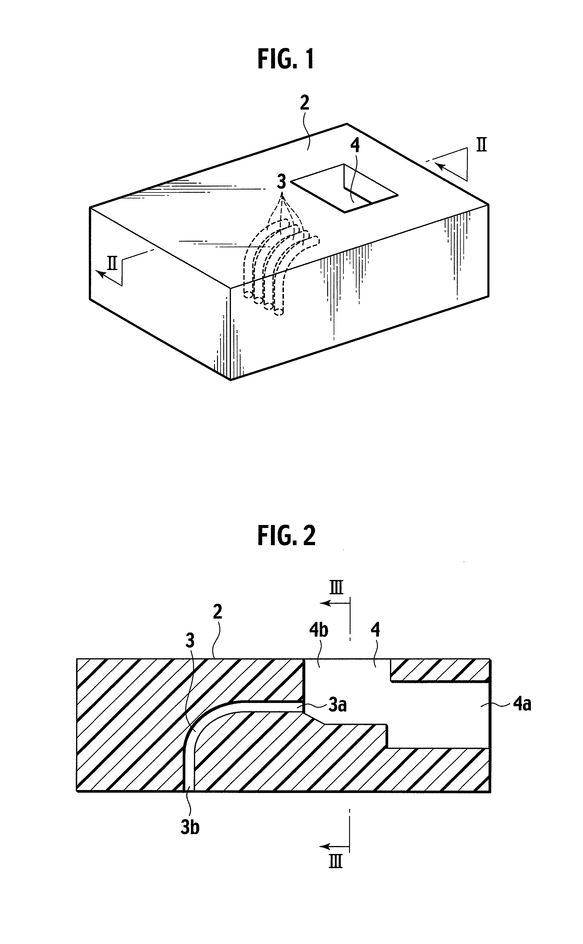
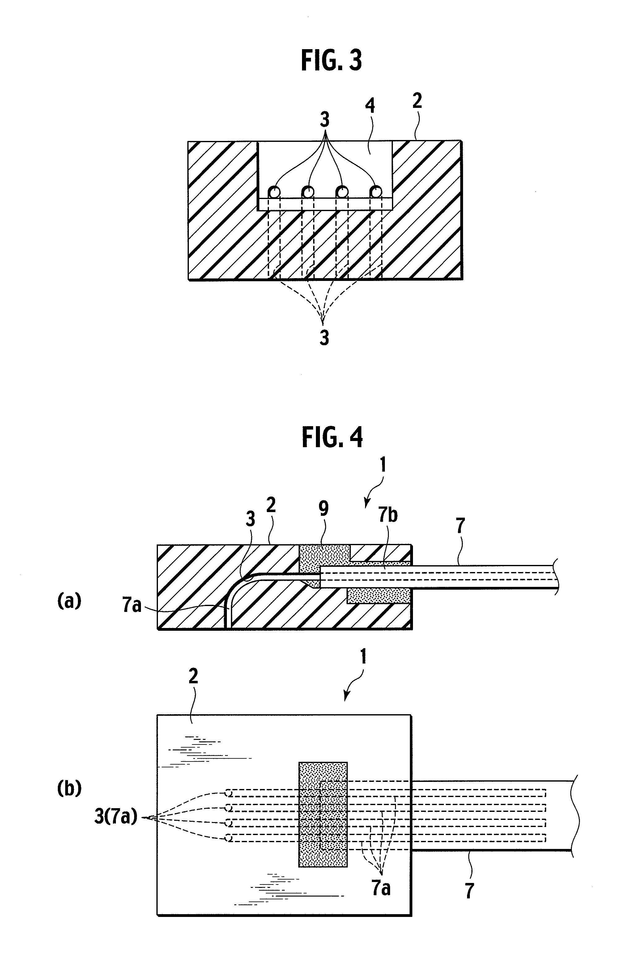
[0030]A first embodiment of the present invention will be described with reference to the drawings of FIG. 1 through FIG. 3. While these drawings illustrate an example of an optical fiber tape 7 including four cores, the number of cores may be arbitrary. Meanwhile, in the following description, sometimes the right direction in FIG. 2 may be referred to as “rearward”, the left as “forward”, the upper as “upper” or “upward”, and the lower as “lower” or “downward”.
[0031]A connector main body 2 is formed in a rectangular parallelepiped having a hollow portion 4 made of any synthetic resin such as epoxy or PPS for example, and is comprised of optical fiber holes 3 directed from a first direction (rearward of the connector main body) to a second direction (forward of the connector main body) and curving at the midway portion therebetween. The hollow portion 4 has an optical fiber tape entrance 4a opened rearward for insertion of an optical fiber tape 7 and an adhesive filling window 4b op...
second embodiment
[0043]While in the aforementioned embodiment the optical fiber holes 3 within the connector main body 2 are, as shown in FIG. 7(a) in an enlarged view, made to be circular holes, optical fiber holes 3′ having triangular cross sections as shown in FIG. 7(b) may be applicable. In this case, the optical fibers 7a are guided by faces on both sides of the vertexes of the triangular cross sections, thereby curving along the optical fiber holes 3′ to reach the exit portions thereof.
[0044]Alternatively, the connector main body 2 may have, instead of independent optical fiber holes, only a single curving hole 13 in which four guiding slot 13a communicate with each other via a common space portion 13b as shown in FIG. 7(c).
third embodiment
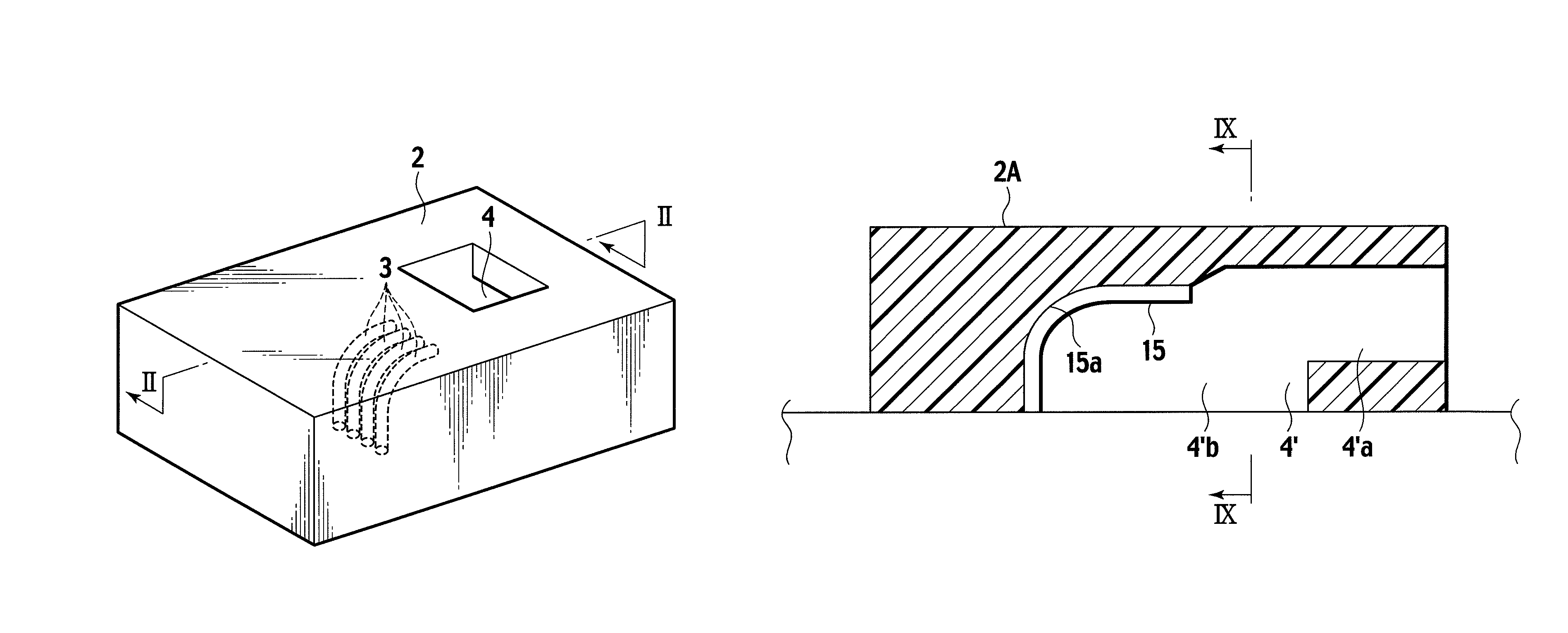
[0045]Further, in a connector main body 2A as shown in FIGS. 8-10, a wall face in front of a hollow portion 4′ may be made curved to be a wall face 15 and the connector main body 2A may have guiding slots 15a having V-shaped cross sections along the curved wall face 15. Formation of exposed slots having V-shaped cross sections is readily achieved on the basis of general knowledge of a skilled person.
[0046]In this case, as inserting the optical fiber tape 7 through the optical fiber tape entrance 4a′, housing the exposed optical fibers 7a in the respective guiding slots 15a on the curved wall face 15 and pressing them forward, the ends of the optical fibers 7a are made curved along the guiding slots 15a to reach positions opposed to the respective photoelectric devices. Then the optical fibers 7a are secured along the guiding slots 15a.
[0047]Subsequently adhesive is filled in the hollow portion 4′ so as to fix the optical fibers 7a and the covering 7b of the optical fiber tape 7.
PUM
 Abstract
Description
Claims
Application Information
 - R&D
- Intellectual Property
- Life Sciences
- Materials
- Tech Scout
- Unparalleled Data Quality
- Higher Quality Content
- 60% Fewer Hallucinations
Browse by: Latest US Patents, China's latest patents, Technical Efficacy Thesaurus, Application Domain, Technology Topic, Popular Technical Reports.
© 2025 PatSnap. All rights reserved.Legal|Privacy policy|Modern Slavery Act Transparency Statement|Sitemap|About US| Contact US: help@patsnap.com


