[0014]Other features and advantages of the disclosure will appear upon reading the following detailed description of exemplary embodiments of the disclosure, provided solely for information and with reference to the appended drawings, as follows:
[0049]An exemplary varistor can be used as a protective component of a device protecting an electrical installation from surges have the following exemplary features. It comprises, in addition to the varistor, a thermal disconnector, comprising a mobile contact suitable of going from a closed position to an open position to disconnect the varistor.
[0057]FIGS. 2A, 2B illustrate front and profile views of a protective cartridge in accordance with an exemplary embodiment.
[0017]FIGS. 3A, 3B illustrate an inner volume defined by the case of the cartridge in accordance with an exemplary embodiment;
[0018]FIG. 4 illustrates a mobile contact of the protective device in the closed position in accordance with an exemplary embodiment;
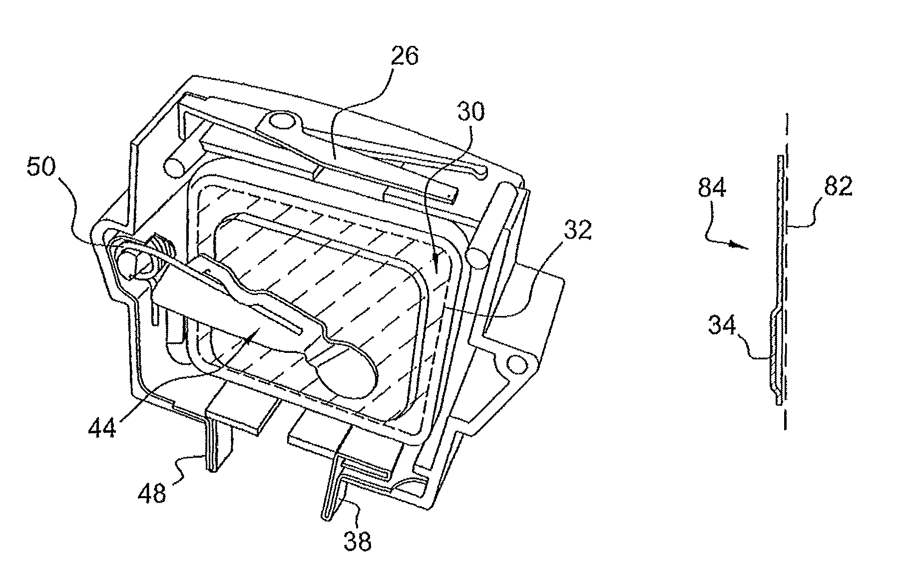
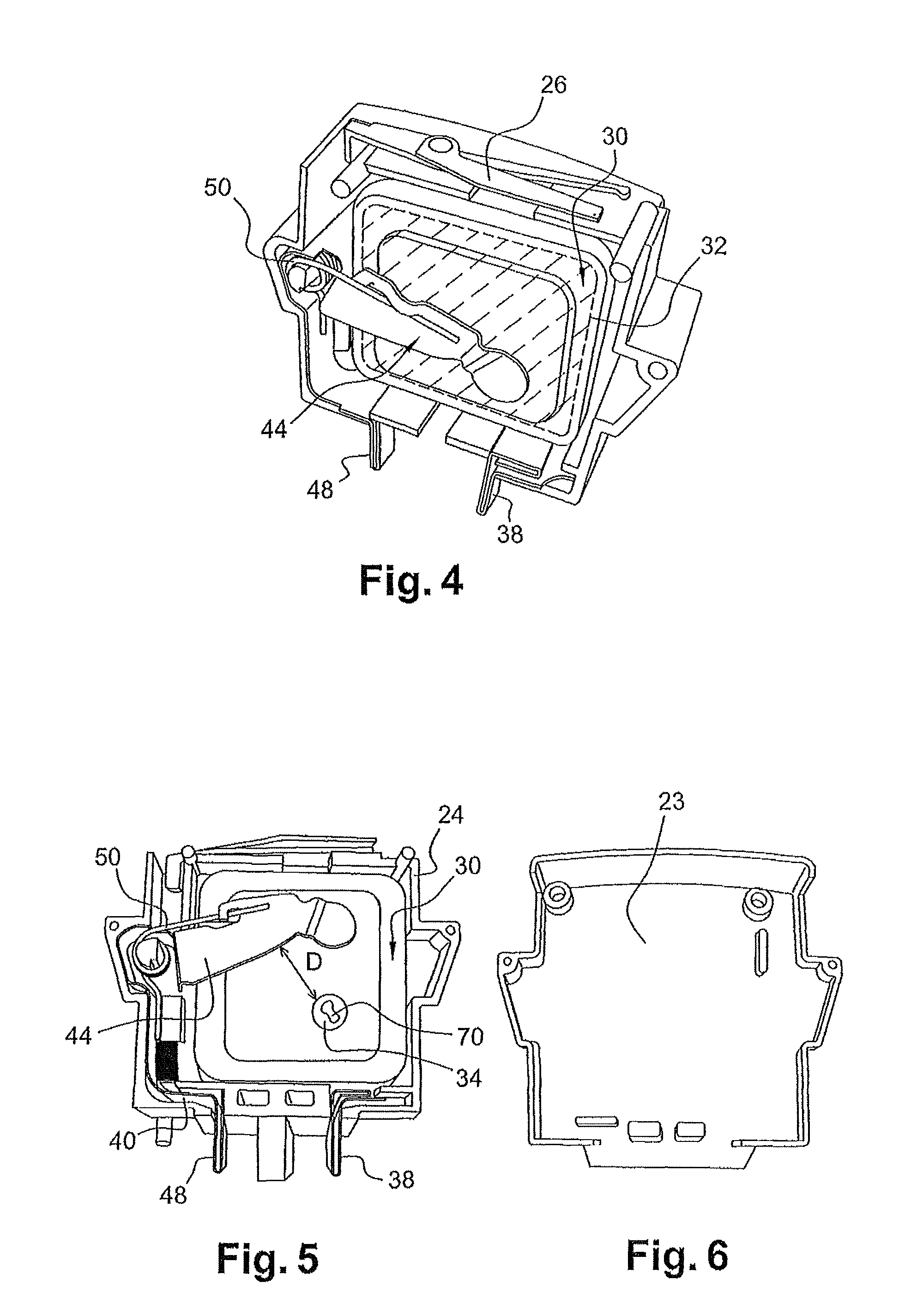
[0062]FIGS. 5 and 6 illustrates a mobile contact of the protective device in the open position and a diagram of the removed part of the case in accordance with an exemplary embodiment. FIG. 5 shows the same protective device with the contact blade 44 in the open position. The contact blade 44 can be disconnected from the pole 34 of the varistor 30. In this position, the pole 34 of the varistor 30 is no longer connected to the terminal 48.
[0020]FIG. 7 illustrates a front view of the varistor housed with the rest of the protective device in the cartridge in accordance with an exemplary embodiment;
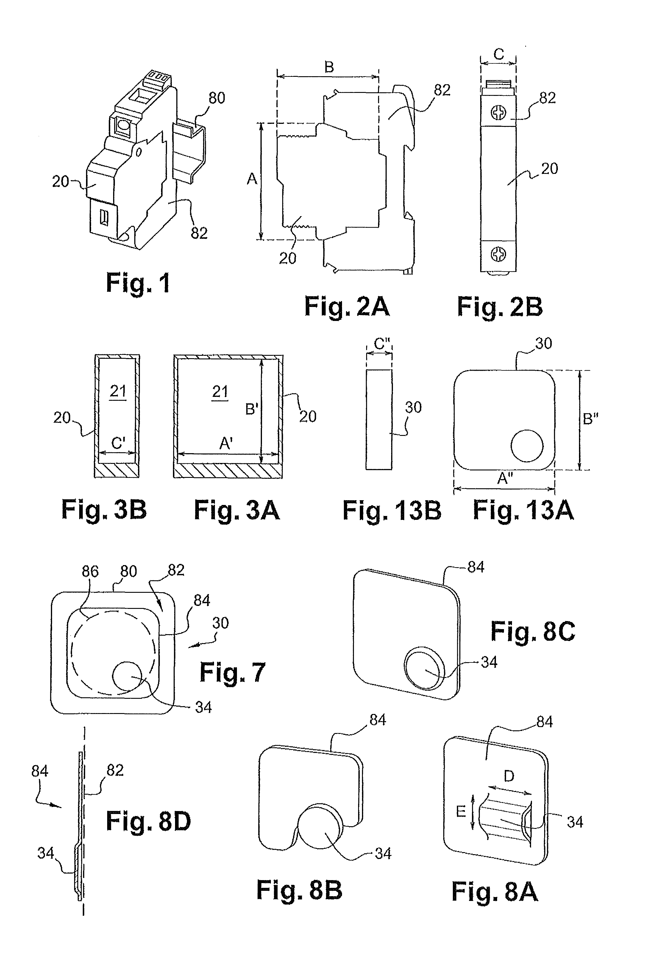
[0021]FIGS. 8A, 8B, and 8C each illustrate a perspective view of an electrode of the varistor in accordance with an exemplary embodiment;
[0022]FIG. 8D illustrates a profile view of the electrode of the varistor;
[0023]FIGS. 9 and 10 illustrate a profile and perspective view of an electrical contact piece in accordance with an exemplary embodiment;
[0024]FIGS. 11A and 11B illustrate a cross-sectional view of a protective device and its equivalent electrical diagram in accordance with an exemplary embodiment;
[0025]FIGS. 12A and 12B illustrate a cross-sectional view of an a protective device with split thermal disconnectors and its equivalent electrical diagram in accordance with an exemplary embodiment;
[0026]FIGS. 13A and 13B illustrate front and profile views of a protective component to be housed in an inner volume of a cartridge in accordance with an exemplary embodiment;
[0027]FIGS. 14A, 14B, 14C, 15A, 15B, and 16A illustrate different views of a protective device with two protective components in accordance with an exemplary embodiment;
[0028]FIG. 16B illustrates an equivalent electrical diagram of a protective device with two protective components in accordance with an exemplary embodiment;
[0029]FIGS. 17A and 17B illustrate a protective device with a protective component having two non-linear blocks for a photovoltaic installation in accordance with an exemplary embodiment.
[0047]The disclosure also relates to an exemplary varistor, comprising at least two connection poles and a block having a non-linear electrical resistance whereof the value varies as a function of the voltage applied to the two connection poles. The block for example has a metal oxide base, the varistor then forms a metal oxide varistor (MOV). The varistor also comprises a conductive plate forming a contact electrode with the block, said conductive plate being arranged on a main face of the block. Said conductive plate has a protruding part forming one of the connection poles of the varistor.
[0048]An exemplary varistor can also include an electrically insulating coating applied at least to the assembly formed by the main face of the block on which the conductive plate is arranged. Moreover, the protruding part of the plate forming the connection pole emerges outside the electrically insulating coating. This part forming the pole then has a braze surface that extends above the electrically insulating coating for electrical connection of the pole. Furthermore, said protruding part forming the connection pole is connected to the rest of the plate over at least half of its perimeter.
[0049]An exemplary varistor can be used as a protective component of a device protecting an electrical installation from surges have the following exemplary features. It comprises, in addition to the varistor, a thermal disconnector, comprising a mobile contact suitable of going from a closed position to an open position to disconnect the varistor.
[0041]The disclosure is also directed to a device for protecting an electrical installation from surges. The device comprises a varistor or a set of varistors, a thermal disconnector, comprising a mobile contact suitable to move from a closed position to an open position to disconnect the varistor or one of the varistors of the assembly, wherein the mobile contact is kept in the closed position by a thermofusible braze fastening the mobile contact on the braze surface of the protruding part forming the connection pole of the varistor. The thermal disconnector is provided to make the mobile contact move to the open position when the thermofusible braze melts, and the mobile contact is provided to move from the closed position to the open position, parallel to the main face of the block of the varistor and away from the electrically insulating coating of the varistor.
[0049]An exemplary varistor can be used as a protective component of a device protecting an electrical installation from surges have the following exemplary features. It comprises, in addition to the varistor, a thermal disconnector, comprising a mobile contact suitable of going from a closed position to an open position to disconnect the varistor.
[0052]The arrangement of the pole protruding and emerging from the electrically insulating coating can ensure that the mobile contact, initially in the closed position (e.g., welded to the braze surface of the pole), performs the movement parallel to the main face of the block of the varistor while remaining at a distance from the insulating coating. Thus, the movement towards the open position can be done without friction of the mobile contact on the electrically insulating coating, which makes it possible to improve the interruption capacity, as demonstrated in more detail in the continuation of this document. The arrangement of the pole protruding and emerging from the electrically insulating coating of the varistor therefore can allow the protective device to benefit from an improved interruption capacity in a reduced bulk.
[0053]The connection of the part forming the pole to the rest of the plate over, for example, at least 50% of the perimeter of the pole can ensure effective heat conduction from the plate towards the pole. Thus, the varistor previously described can cause an increase in the reaction time of the varistor, which is the time that elapses between the beginning of heating of the varistor and the temperature increase of the pole of the varistor. The improvement to this reaction time can limit the current passing through the varistor at the time of the thermal disconnection at a leakage current of the varistor not having too strong an intensity relative to the improved interruption capacity of the device.
[0054]The arrangement of the pole protruding and emerging from the electrically insulating coating of the varistor with a connection to the rest of the plate over at least half of the perimeter of the pole makes it possible to have the protective device have, in a reduced bulk, an interruption capacity sufficient to interrupt the electrical currents passing through the varistor at the time of the thermal disconnection. The varistor thus can ensure a reliable disconnection in case of thermal disconnection for overvoltage protection devices that have a reduced bulk.
[0055]FIG. 1 illustrates a perspective view of a protective cartridge 20 of a low-voltage electrical installation in accordance with an exemplary embodiment. The protective cartridge 20 comprises a protective device for protection from over voltages. This protective cartridge 20 can be pinned on a base 82, which can be mounted on a DIN rail with a standardized electric board. Pinning the cartridge 20 on a base 82 facilitates a connection of the protective device to the low-voltage electrical installation to be protected. As provided herein, “low-voltage electrical installation” refers to equipment with an assigned RMS voltage up to, for example, 1,000 V in alternating current or up to, for example, 1,500 V in direct current. The fastening on a DIN rail is standard for such electrical installations. The described device for protecting from overvoltages is also adapted to the protection of photovoltaic generator installations.
[0058]FIGS. 2A and 2B, respectively, illustrate one of the main faces of the cartridge 20 and the edge of the cartridge 20. The cartridge 20, which houses the protective device has outer dimensions A×B×C smaller than or equal to 57×50.5×17.6 mm, for example.
[0059]FIGS. 3A and 3B illustrate the inner volume 21 defined by the case of the cartridge 20 housing the protective device in accordance with an exemplary embodiment. FIG. 3A shows a cross-section of the case along one of the main faces of the case. FIG. 3B shows a cross-section of the case along the edge of the case. The cartridge 20 intended to house the protective device thus has a parallelepiped inner volume 21 having dimensions C′×A′×B′ smaller than or equal to 15×42×43 mm, for example.
[0060]Described below are various exemplary features, which enable the protective device to have a compact structure, thereby allowing it to be housed in the inner volume 21.
[0061]FIG. 4 illustrates a mobile contact of the protective device in the closed position in accordance with an exemplary embodiment. As shown in FIG. 4, the cartridge 20 houses the protective device, which includes a varistor 30 as a protective component, and a conductive contact blade 44 that forms a mobile contact of a thermal disconnector. Alternatively, the mobile contact can be formed by a braid or a wire or other suitable structure as desired, to ensure the connection of the protective component to the electrical installation. The protective device 30 includes two terminals 38 and 48 for connecting the device to the electrical installation. The varistor 30 has two poles each connected to a respective one of the terminals 38 and 48. FIG. 4 shows the protective device with the contact blade 44 in the closed position. The contact blade 44 is electrically connected to the pole 34 (visible in FIG. 5) of the varistor 30. The pole 34 can thus constitute a fixed contact of the thermal disconnector. The pole 34 is connected to the terminal 48 via the contact blade 44. Moreover, the contact blade 44 is elastically stressed by a torsion spring 50. The connection of the terminals 38 and 48 to the electrical installation to be protected can be established, in this example, via the base 82 previously described with reference to FIG. 1. The terminals 38 and 48 can be implemented as male terminals, such as pins or other suitable structure as desired.
[0063]FIGS. 5 and 6 illustrate the cartridge 20 with the case 20 of the cartridge open. The case is made up of an upper flange 23 shown in FIG. 6 and a lower flange 24 shown in FIG. 5. The compactness of the protective device enables the formation of an “equipped cradle” with the lower flange 24. FIG. 5 illustrates the contact blade 44 in the disconnected state.
[0064]The thermosensitive element of the thermal disconnector can be a thermofusible braze 70 via which the contact blade 44 is at the pole 34 of the varistor 30. This braze can be visible on the pole 34 of the varistor 30 as shown in FIG. 5. The braze 70 ensures the electrical connection between the blade 44 in the closed position and the terminal 34 until the protective component 30 reaches the threshold temperature (for example 140° C.), which is indicative of a failure of the varistor 30. When the varistor 30 reaches the threshold temperature, the braze 70 melts and the end of the contact blade 44 that was connected to the pole 34 of the varistor 30 moves away from the latter under the action of the spring 50. As a result, the electrical connection between the contact blade 44 and the pole 34 is broken.
[0065]In the exemplary embodiments of the present disclosure, the protective device can face surge situations without a risk of explosion or fire outbreak, at least if the protective device is likely to be subjected to such surge conditions. For example, the exemplary embodiments can be designed to satisfy the tests provided by the UL standard, paragraph 39 or by the UTE guide, paragraph 6.7.4. To this end, the disclosed exemplary embodiments provide fast thermal disconnection of the varistor 30. In these surge situations, current passing through the varistor increases gradually until the varistor goes into a steady-state short-circuit.
[0066]The time the varistor 30 spends in short circuit can depend, for example, on a ratio between the surge and the maximum operating voltage allowable by the varistor and the electric behavior of the varistor (e.g., variation of the resistivity of the varistor as a function of the voltage applied to it). On one hand, when the ratio between the surge and the maximum allowable voltage of the varistor 30 is high, the time spent by the varistor 30 in short circuit is low. On the other hand, when the behavior of the varistor is strongly non-linear (e.g., the resistivity of the varistor varies very sharply with the increase of the voltage applied to it), the time spent by the varistor 30 in short circuit is low. It is then possible to choose the varistor as a function of these different features to increase the time spent in steady-state short circuit under the in use conditions of the varistor. The current surge phase can be accompanied by an increase in the temperature of the varistor 30, during the time spent by the varistor in short circuit. The exemplary thermal disconnector can be designed to ensure a disconnection in the transitional phase of the behavior of the varistor before the current passing through it becomes too high to be able to be interrupted by the thermal disconnector. This design involves a fast detection of the increase in the temperature of the varistor.
[0067]Various technical characteristics of the exemplary embodiments of the present disclosure contribute to obtaining this fast disconnection.
[0069]FIG. 7 illustrates a front view of the varistor housed with the rest of the protective device in the cartridge in accordance with an exemplary embodiment. FIG. 7 shows a perspective view of the varistor 30 seen perpendicularly to the plane of its main face 32. The pole 34 can be arranged inside a central area on the main face 32. This central area is represented by an imaging circle 86 in broken lines in FIG. 7. The central area can be situated inside the imaginary circle 86 centered on said main face 82 of the block 80 and having a diameter equal to 75%, for example, of the diameter of the circle drawn on the main face 82 of the block 80. The arrangement of the pole 34 on the main face 32 in the central area can ensure fast detection, by the thermofusible braze 70, of the increase in the temperature of the varistor 30 during the transitional phase where the current passing through it increases. The runaway of the varistor 30 can cause an increase in the temperature first in the deteriorated zones of the varistor 30. These deteriorated zones correspond to zones of the varistor 30 having uncontrolled design flaws. The location of these zones is not known a priori, such that the thermal runaway of the varistor starts in an undetermined area. The arrangement of the pole 34 in the central area can establish that the pole 34 is statistically closest to the area where the thermal runaway of the varistor begins.
[0070]The pole 34 of the varistor 30 can advantageously extend along the main face 32, and not protrude perpendicular thereto. As a result, the braze 70 is done on the pole 34 at a brazing surface that is parallel to the main face 32 of the varistor 30. The braze 70 has its thickness in a direction perpendicular to the main face of the protective component. As a result, the entire braze 70 is as close as possible to the varistor 30 and can establish immediate communication with it regarding the temperature of the varistor 30. This measure can be advantageous relative to known solutions in which the pole of the protective component forming the fixed contact of the thermal disconnector extends in a plane perpendicular to the main face of the protective component. The braze can extend along the perpendicular plane and part of the braze can be kept at a distance from the protective component. When the protective component fails, the braze is first stressed thermally in a portion closest to the protective component. The delay of a temperature increase of the varistor arriving at the portion of the braze that is farthest from the protective component 30, which can slow the thermal disconnection.
[0071]Moreover, the speed of thermal disconnection can also be improved by the exemplary varistor 30 of the present disclosure, through the electrode forming the pole of the varistor, which serves to transmit the heat given off by the varistor to the thermosensitive element of the thermal disconnector.
[0072]Thus, the electrode of the varistor can be formed by a conducting plate 84, as shown in FIG. 7. The varistor 30 can also include a block 80. The block 80 has an electrical resistance which varies as a function of the voltage applied to the block 80. This block 80 can establish the active part of the varistor 30 and can be used to limit the overvoltages by having a low resistance for overvoltages with high amplitudes like those occurring during lightning. The conducting plate 84 can be arranged on a main face 82 of the block 80. The main faces of the block 80 correspond to the main faces of the varistor 30. The plate 84 has a protruding part forming one of the connection poles 34 of the varistor. Similarly, a second pole 36 of the varistor 30 can be formed by a protruding part of a conducting plate arranged on another main face of the block 80 of the varistor 30.
[0073]The varistor 30 can include an electrically insulating coating applied on the assembly formed by the main face 82 of the block 80 and the plate 84. Thus, the assembly formed by the main face 82 of the block 80 and the plate 84 can be electrically insulated from its surrounding environment, including the mobile contact of the protective device. In an exemplary embodiment, the assembly formed by the block 80 and the plate 84 can be completely coated with the electrically insulating coating through which the different connection poles of the varistor also emerge to produce an electrical connection with the rest of the protective device, for example, with the contact blade 44.
[0074]The protruding part forming the pole 34 can emerge outside the electrically insulating coating to allow an improvement of the interrupting capacity as described below.

