Hydraulically operated valve actuation and internal combustion engine with such a valve actuation

a fluid-operated valve and valve actuation technology, which is applied in the direction of valve arrangements, machines/engines, non-mechanical valves, etc., can solve the problems of high energy consumption, disadvantages or problems of fluid-operated valve drives, and disadvantages of said systems, so as to reduce the demand for engine oil, reduce the poisoning of exhaust-gas aftertreatment, and reduce the effect of service li

Inactive Publication Date: 2013-02-26
EMPA EIDGENOESSISCHE MATERIALPRFUNGS & FORSCHUNGSANSTALT
View PDF31 Cites 1 Cited by
  • Summary
  • Abstract
  • Description
  • Claims
  • Application Information

AI Technical Summary

Benefits of technology

[0015]A further advantage of the invention is that the demands on the engine oil of engines with a mechanical valve drive are defined primarily by the camshaft drive of the valves, and necessitate the corresponding addition of additives to the engine oil. Said addition of additives is based partially on substances which are detrimental to the exhaust-gas aftertreatment (catalytic converter poisons such as phosphorous or zinc). Without measures to reduce the poisoning of the exhaust-gas aftertreatment, the high service lives which will be demanded in future in exhaust-gas legislature cannot be adhered to. To eliminate said oil-based damage to the exhaust-gas aftertreatment arrangement, complex measures (for example separate lubricating oil circuits for camshaft and valve drive on the one hand and crankshaft and pistons on the other hand) are under discussion. Hydraulically or pneumatically operated valve drives considerably reduce the demands on the engine oil in relation to mechanically operated valve drives, which ultimately also has a positive effect on the service life of the exhaust-gas aftertreatment arrangement.
[0016]In another embodiment, said aspect of the invention is characterized in that the movement sequence of the engine valve is monitored with regard to its movement travel by means of a sensor. At all times, the deviation of the effective location of the engine valve from its setpoint location according to specification is determined and measured by means of a control unit for said engine valve. The change in the cross section of the corresponding second fluid valve means is calculated such that the valve returns to the position according to specification. According to said aspect of the invention, the system is self-correcting by means of said function, and influences which can unfavorably vary the movement of the engine valve need not be taken into consideration.
[0017]According to a further aspect of the invention, the recuperation of the above-described valve drive, that is to say the conditioned pressure prevailing in the second reservoir, is used exclusively or additionally for the valve drive of a different valve drive of the internal combustion engine. Since the working pressures for the fluid pressure of the outlet valves of an internal combustion engine should conventionally be higher than the working pressures of the inlet valves—since the outlet valves must operate at most at least briefly counter to the combustion gas pressure—a design is then particularly advantageous in which, in the internal combustion engine, the valve drives of the outlet valves are designed according to the invention and the recuperation energy thereof is designed for the lower fluid pressures of the valve drives of the inlet valves. In this case, it is possible for a pressure arrangement according to the prior art to be provided for the valve drives of the inlet valves, in which only one common pressure reservoir—specifically the second pressure reservoir of the outlet valves—is provided in addition to the base reservoir. Said second pressure reservoir would then ideally not additionally need to be supplied with pressure.
[0018]The elements mentioned above and the elements claimed and described in the following exemplary embodiments, and which are to be used according to the invention, are not subject to any particular exceptions with regard to their size, shaping, material usage and their technical design, such that the selection criteria known from the respective application may be used without restriction.

Problems solved by technology

Said proposal has proven not to be especially advantageous since the valve control arrangement cannot be set up very precisely with a manageable amount of expenditure.
Said system is however very complex and can only be used to a limited extent on account of the complex fluid supply control.
In relation to conventional mechanically driven valve drives, fluid-operated valve drives basically have the disadvantage or the problem of higher energy consumption, since the power of the internal combustion engine is then lost.
The type of recuperation proposed therein is entirely suitable for use for example in a forklift truck etc. but, on account of its complexity, would appear to be entirely unsuitable for use for driving an actuating piston for an internal combustion engine, and would not appear to be a model for solving the above-described problem.
The rudimentary recuperation as proposed in US 2004 / 107699 A1 has the particular disadvantage that the recovered pressure must be used as it accumulates.

Method used


Image

  • Hydraulically operated valve actuation and internal combustion engine with such a valve actuation
  • Hydraulically operated valve actuation and internal combustion engine with such a valve actuation
  • Hydraulically operated valve actuation and internal combustion engine with such a valve actuation

Examples


Embodiment Construction

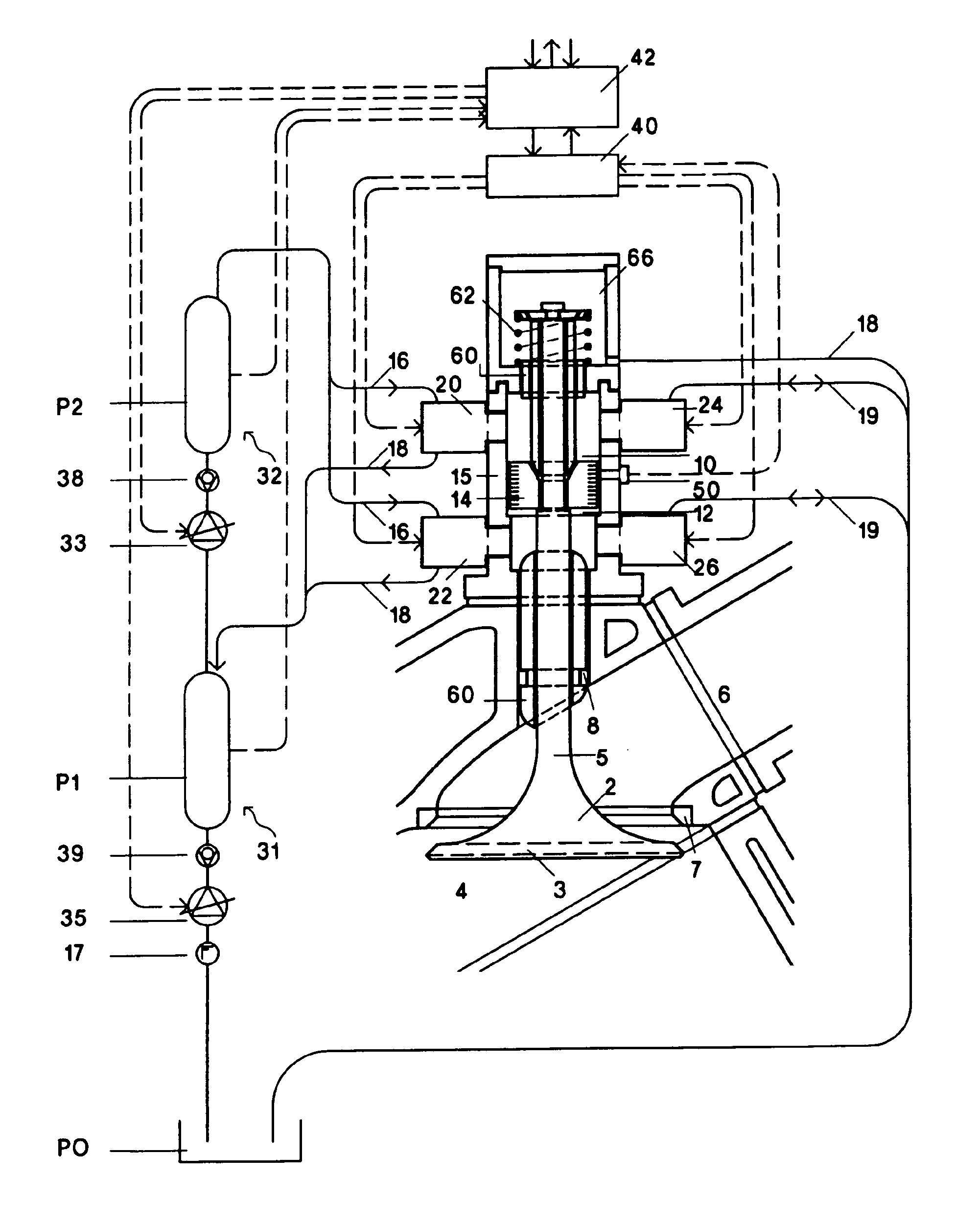
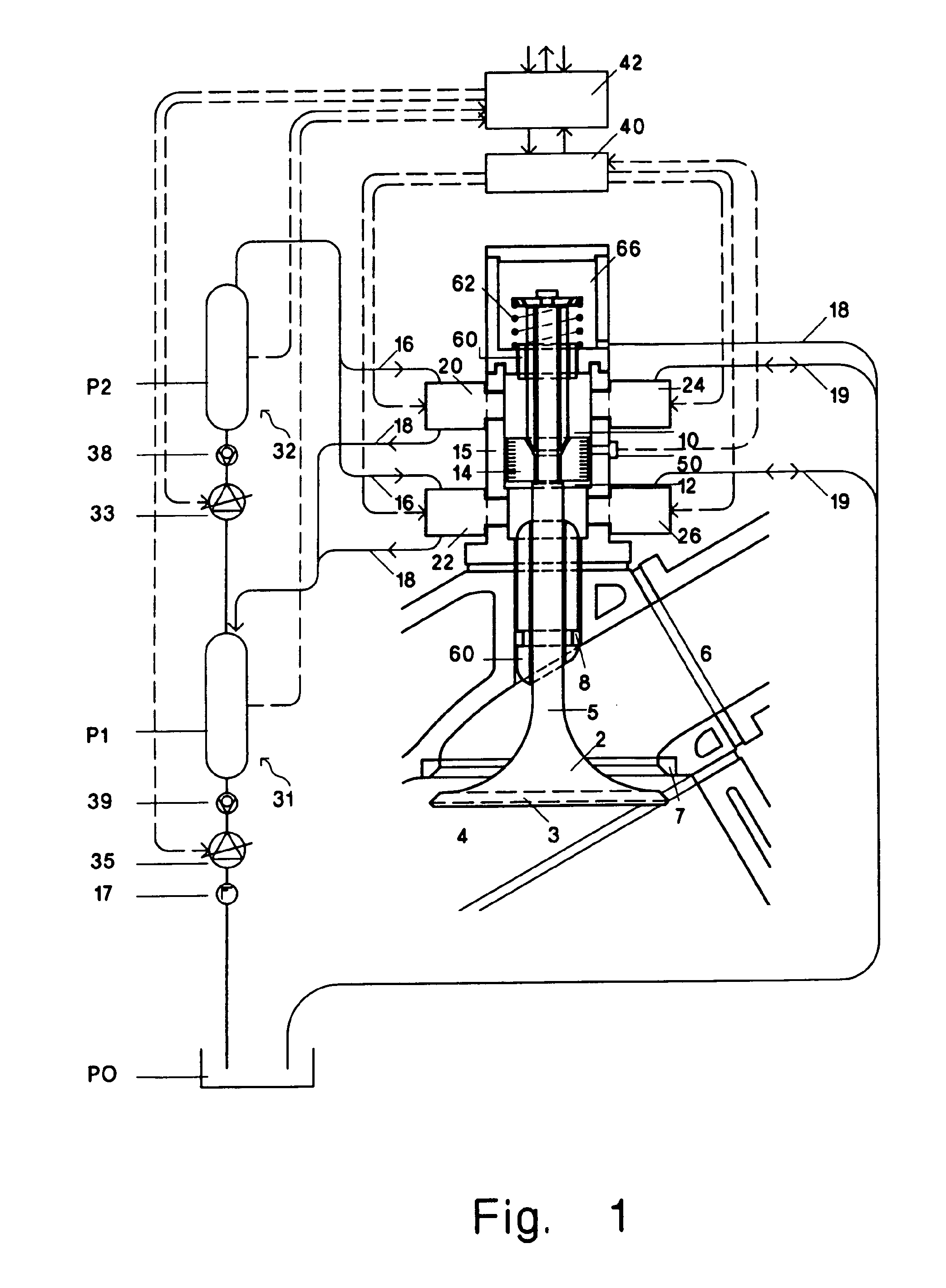
[0022]FIG. 1 illustrates a valve arrangement according to a first exemplary embodiment of the present invention, having an engine valve 2 and having a driving device (actuator) for said engine valve. The valve 2 comprises—in the usual way—a valve plate 3 which is adapted to a valve seat ring 7 in order to close off the engine bay. When the valve 2 is open, that is to say when the valve is lowered, the combustion chamber 4 of the engine is connected to the combustion gas duct 6. It is said connection that is to be controlled or regulated by means of the valve drive.

[0023]The engine valve 2 bears, on its valve shank 5, an actuating piston 14 which is fixedly connected thereto and which has an upper active surface, which is formed on the upper side of the actuating piston 14, and also a lower active surface, which is formed on the underside of the actuating piston 14. Together with the pressure chamber housing 15 in which the actuating piston 14 is arranged so as to be movable upward a...


PUM


Abstract

According to the invention, recuperation may be optimized for a hydraulically-operated gas exchange valve by provision of two fluid-filled pressure chambers and a movable regulating piston with two active faces each defining one of the pressure chambers. The pressure chambers are each connected to two hydraulic valves of which the first hydraulic valves may be pressurized from a first pressure reservoir and the second hydraulic valves may be connected to a base pressure reservoir. The first hydraulic valves may furthermore be connected to a second pressure reservoir. A control or regulation device switches the valves, from a rest position in a first accelerating phase and a braking phase. The second pressure reservoir is provided as pressure buffer for providing the pressure in the first pressure reservoir and / or for providing pressure for the fuel pump and / or for the fuel supply to an internal combustion engine and / or for providing pressure for a further gas exchange valve in the same or another combustion cylinder of the internal combustion engine.

Description

[0001]The application claims priority of PCT application PCT / EP2008 / 009772 having a priority date of Nov. 23, 2007, the disclosure of which is incorporated herein by reference.TECHNICAL FIELD[0002]The invention relates to a fluid-operated valve drive, in particular for a gas exchange valve in a combustion cylinder of an internal combustion engine and to an internal combustion engine having such a valve drive.BACKGROUND OF THE INVENTION[0003]Fluid-operated valve drives, in particular for gas exchange valves in a combustion chamber of an internal combustion engine, which within the context of this invention encompass both hydraulically and also pneumatically operated valve drives, have long been known. Firstly, said valve drives were used to replace a camshaft-controlled opening of an engine valve, while the closing of the valve continued to be provided by means of a spring mechanism. Such systems are known for example from the German laid-open specification 1,944,177. However, bidire...

Claims


Application Information

Patent Timeline
Patent Type & Authority Patents(United States)
IPC IPC(8): F01L9/02F01L1/30F01L1/34F01L9/10F01L9/16
CPCF01L9/02F01L9/026F01L13/00F01L2820/045F01L9/16F01L9/10
Inventor RUST, BERNHARDSOLTIC, PATRIKBACH, CHRISTIAN
Owner EMPA EIDGENOESSISCHE MATERIALPRFUNGS & FORSCHUNGSANSTALT
Why Eureka
Try Eureka