Construction machine

a construction machine and axial direction technology, applied in the direction of machines/engines, mechanical equipment, transportation and packaging, etc., can solve the problems of metal higher cost, and inability to absorb the deformation of the bellows in the axial direction of the bellows, so as to achieve the effect of further simplifying the structur

Active Publication Date: 2013-02-26
KOBELCO CONSTR MASCH CO LTD
View PDF18 Cites 22 Cited by
  • Summary
  • Abstract
  • Description
  • Claims
  • Application Information

AI Technical Summary

Benefits of technology

[0013]An object of the present invention is to provide a construction machine having a muffler mounting device that can improve the position adjusting function of a bellows for absorbing assembly errors and can facilitate the position adjusting operation.

Problems solved by technology

During assembly (when the muffler and the exhaust pipe are connected), some assembly errors including that in the axial direction of the bellows can be absorbed by the deformation of the bellows.
This leads to higher cost.
In addition, the bellows is formed of metal and a substantial force is needed to deform it.
Therefore, the position adjusting operation relative to the exhaust pipe is troublesome.

Method used


Image

  • Construction machine
  • Construction machine
  • Construction machine

Examples


Embodiment Construction

[0039]Embodiments of the present invention will be described with reference to FIGS. 1 to 5.

[0040]In the embodiments, the present invention is applied to a hydraulic shovel.

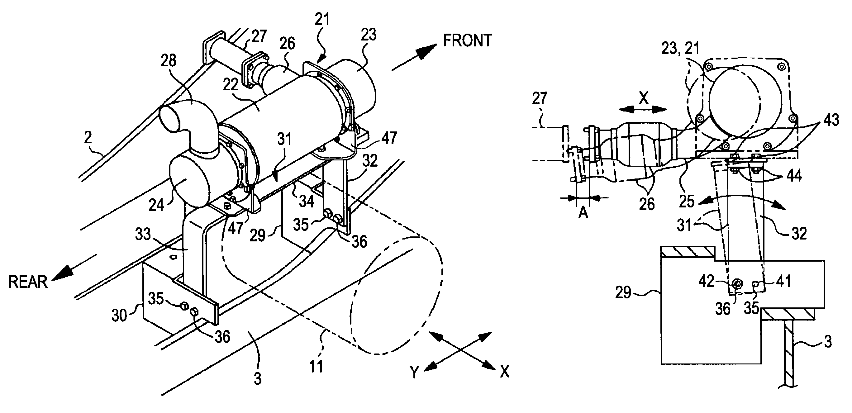
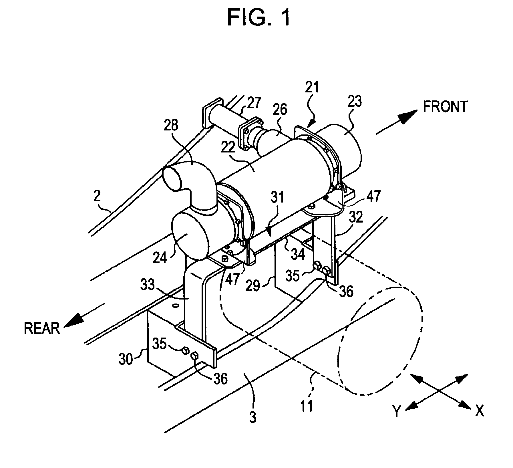
[0041]As in the art described in the related art, an engine room is formed at the rear end of an upper rotating body, an engine is placed in the engine room, a hydraulic pump 11 (shown by long dashed double-short dashed line in FIGS. 1 and 2) is connected to the right side of the engine, and a muffler 21 is placed over the hydraulic pump 11.

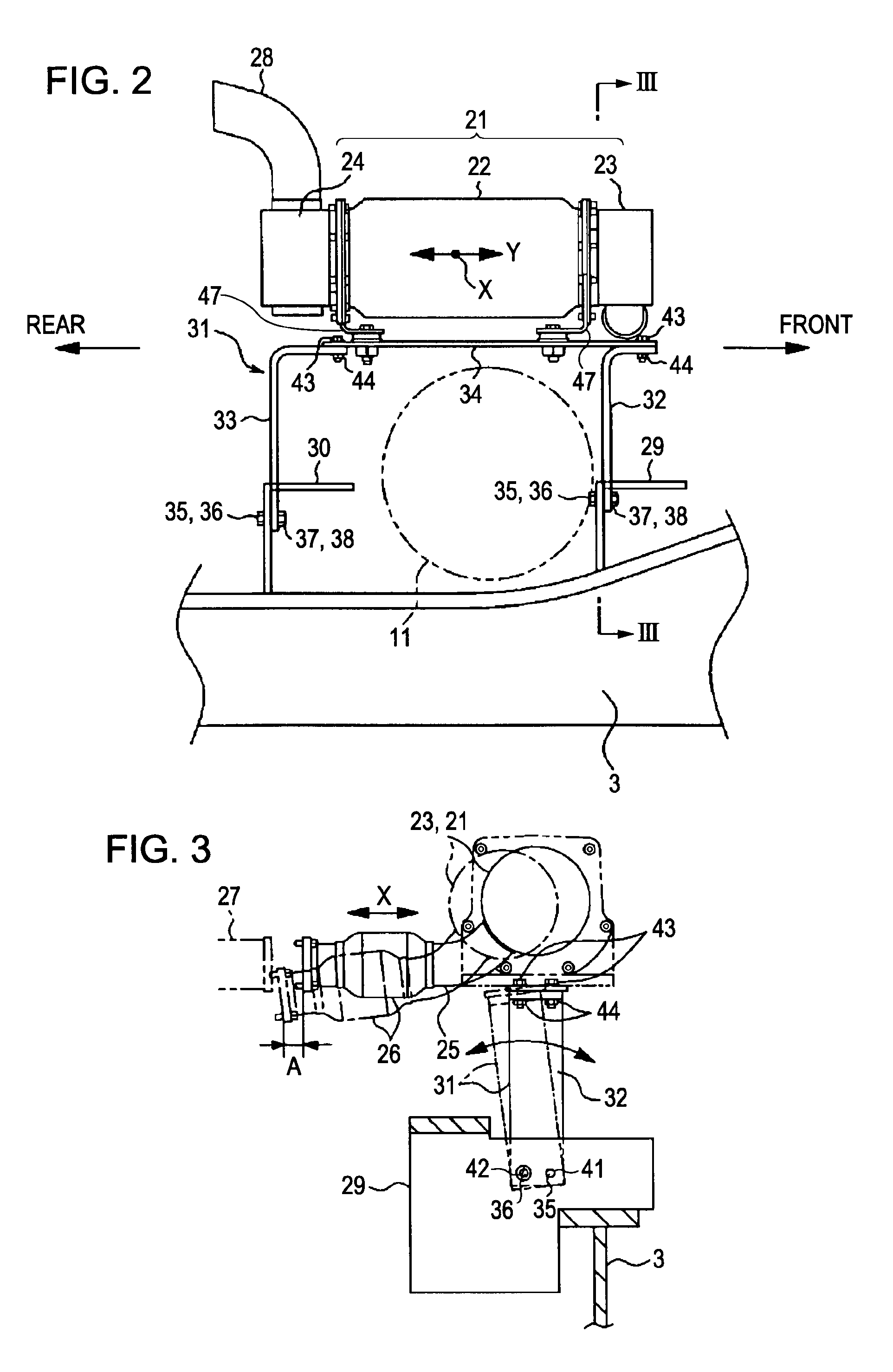
[0042]The muffler 21 includes an exhaust emission control system 22 that removes NOx (nitrogen oxides) and PM (Particulate Matters) from exhaust gas, and silencers 23 and 24 provided on the inlet (engine) side and the outlet side of the exhaust emission control system 22. The exhaust emission control system 22 and the silencers 23 and 24 are flange-connected in the axial direction of the muffler. The inlet side silencer 23 is connected to an introduction tube 25 (shown in FIG....


PUM


Abstract

A gate-shaped muffler mount including front and rear leg portions and a muffler attaching portion is attached to a mounting bracket for supporting an engine with bolts so as to straddle a hydraulic pump. One of mounting holes has a diameter larger than the diameter of the bolt, and the muffler mount is therefore rotatable around the other bolt along the axial direction of a bellows. By this rotation, the bellows can be positionally adjusted in the axial direction relative to an engine exhaust pipe so that assembly errors can be absorbed.

Description

BACKGROUND OF THE INVENTION[0001]1. Field of the Invention[0002]The present invention relates to a construction machine, such as a hydraulic shovel, having a muffler mounting device for mounting a muffler used in an engine exhaust system, in an engine room.[0003]2. Description of the Related Art[0004]A hydraulic shovel will be taken as an example to describe the background art.[0005]FIG. 6 shows an upper rotating body mounted on a lower traveling body. In the figure, reference numeral 1 denotes an upper frame of the upper rotating body. At one end (at the left side end in the figure, the side of this end will hereinafter be referred to as front) of the upper frame 1, a working attachment (not shown) including a boom, an arm, and a bucket is attached.[0006]On the upper surface of the upper frame 1, on both sides of the middle portion in the left-right direction and over substantially the entire length in the front-rear direction, longitudinal plates (also referred to as main frames) ...

Claims


Application Information

Patent Timeline
Patent Type & Authority Patents(United States)
IPC IPC(8): B60K13/04
CPCE02F9/00E02F9/0866
Inventor OKADA, KOJI
Owner KOBELCO CONSTR MASCH CO LTD
Why Eureka
Try Eureka