Wind turbine generator

a wind turbine generator and wind turbine technology, applied in the direction of electric generator control, machine/engine, power distribution line transmission, etc., can solve the problems of communication path blockage and communication becoming unstable, and achieve the effect of improving the communication environmen

Active Publication Date: 2013-02-26
MITSUBISHI HEAVY IND LTD
View PDF4 Cites 7 Cited by
  • Summary
  • Abstract
  • Description
  • Claims
  • Application Information

AI Technical Summary

Benefits of technology

[0010]According to the present invention, the hub-side signal processing unit is provided on the hub side of the slip ring, the nacelle-side signal processing unit is provided on the nacelle side of the slip ring, and the hub-side signal processing unit and the nacelle-side signal processing unit superimpose an information signal on electrical power carried between the hub and the nacelle via the slip ring. This eliminates the need for the slip ring to be provided with a signal line, and therefore even if an increase in the number of channels is required, it is possible to easily increase the number of channels without making a modification to the design of the slip ring.
[0025]According to such a configuration, it is possible to resolve deficiencies such as sound interruptions in audio communication between the nacelle and the tower bottom, in addition to audio communication between the hub and the nacelle, thus enabling an improvement in the communication environment.

Problems solved by technology

However, the hub rotates, and therefore when wireless communication technology is used, depending on the location where the transmission and reception antennas are attached, there are problems such as communication becoming unstable due to the rotation, and the communication path being blocked by the blades.

Method used


Image

  • Wind turbine generator
  • Wind turbine generator
  • Wind turbine generator

Examples


second embodiment

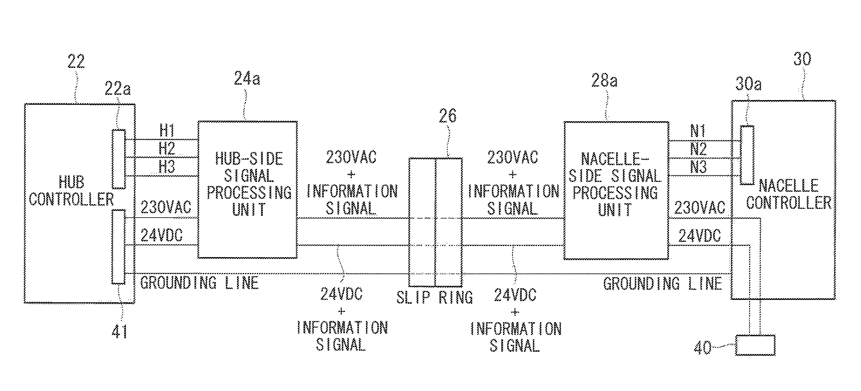
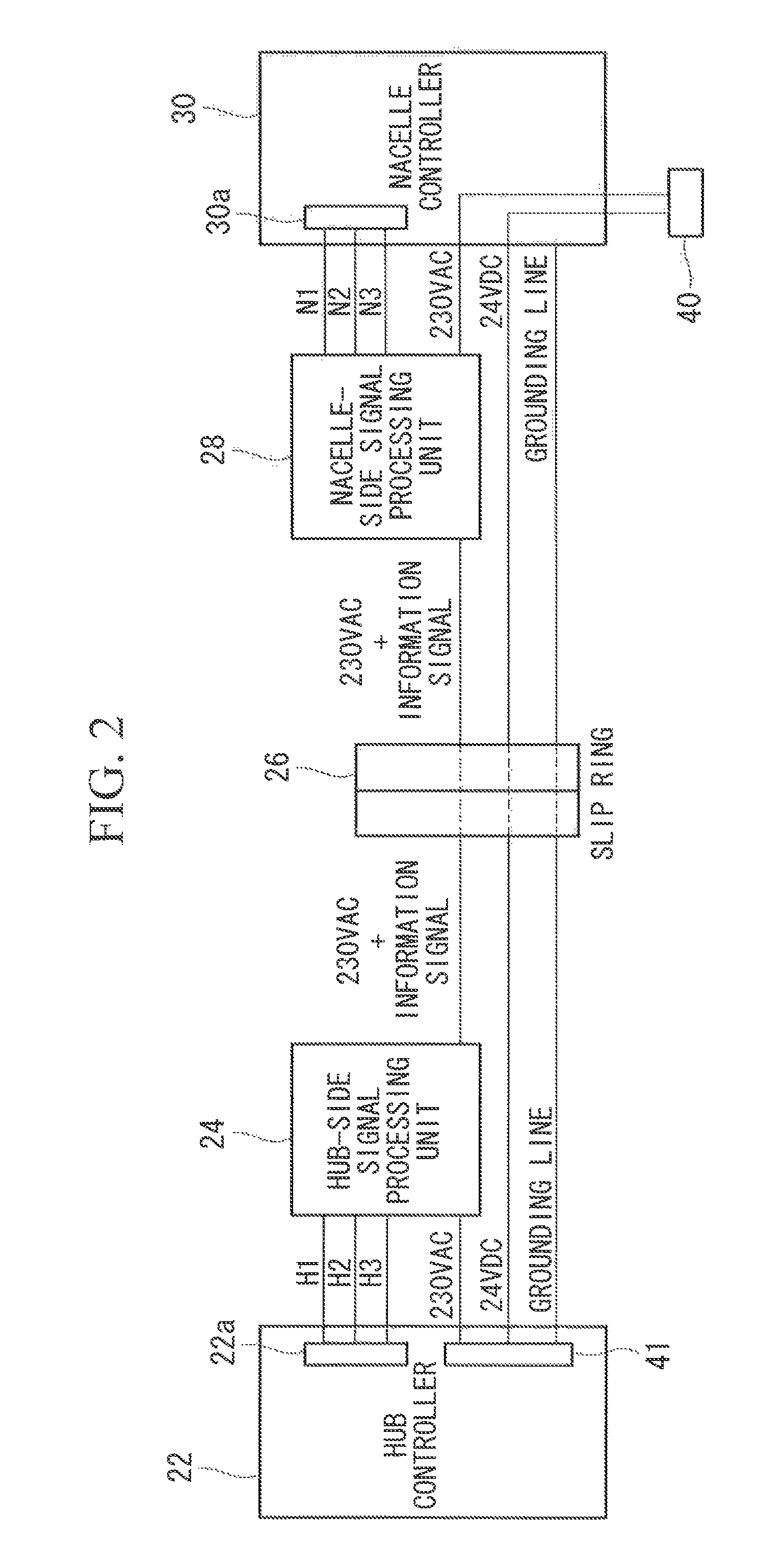
[0049]FIG. 5 is a diagram showing a main configuration related to audio communication between the hub and the nacelle in the wind turbine generator according to the present invention. In FIG. 5, the same reference signs have been given to constituent elements that are similar to those in FIG. 4. As shown in FIG. 5, in the wind turbine generator of the present embodiment, receivers 51 and bells 52 are connected to a hub-side signal processing unit 24a and a nacelle-side signal processing unit 28a. As shown in FIG. 6, each of the receivers 51 includes a microphone 511, a speaker 512, a call button 513, and a hang-up button 514.

[0050]If a worker working in the nacelle desires to communicate with a worker working in the hub, the worker first operates the call button 513 of the receiver 51 connected to the nacelle-side signal processing unit 28a. Upon detecting the operation of the call button 513, the nacelle-side signal processing unit 28a superimposes an information signal indicating ...

third embodiment

[0058]FIG. 7 is a diagram showing a main configuration related to communication between the hub and the nacelle and between the nacelle and the tower bottom in the wind turbine generator according to the present invention. In FIG. 7, the same reference signs have been given to constituent elements that are similar to those in FIG. 6.

[0059]As shown in FIG. 7, a three-phase AC power line (second power line) A for carrying three-phase AC power extends from a generator 70 disposed in the nacelle to a switch panel 71 via the tower, and furthermore extends outside the tower from the switch panel 71. The power line for each phase in the three-phase AC power line A is connected to a tower-side signal processing unit 60 that includes a receiver 51 and a bell 52.

[0060]Also, the nacelle-side signal processing unit 28b is connected to the AC power line 230 VAC and the DC power line 24 VDC, and is connected to the power line for each phase of the three-phase AC power line A. In this way, the nac...


PUM


Abstract

An object of the present invention is to provide a wind turbine generator in which a communication channel can be added in communication between a hub and a nacelle, without making a modification to the design of a slip ring. The present invention provides a wind turbine generator in which communication between the hub and the nacelle is performed by superimposing an information signal onto AC power carried over an AC power line between the hub and the nacelle via the slip ring.

Description

BACKGROUND OF THE INVENTION[0001]1. Field of the Invention[0002]The present invention relates to a wind turbine generator, and in particular to communication performed in a wind turbine generator between a hub and a nacelle, between a nacelle and a tower bottom, and the like.[0003]2. Description of Related Art[0004]Conventionally, in the case where communication is performed in a wind turbine generator between a controller or a measuring apparatus housed in a hub (rotor head) and a device housed in a nacelle, communication channels are provided in a slip ring, and wired data communication is performed, as shown in FIG. 8.[0005]Also, during site installation of a wind turbine generator, maintenance and inspection, and the like, communication needs to be performed between workers in the hub and workers in the nacelle, and between workers in the nacelle and workers at the tower bottom. In such cases as well, similarly to the above-described communication between devices, a telephone li...

Claims


Application Information

Patent Timeline
Patent Type & Authority Patents(United States)
IPC IPC(8): H02J1/00
CPCH04B3/54Y02E10/726H04B2203/5475Y02E10/72
Inventor BABA, MITSUYANISHIMOTO, YASUTAKAKUMAMOTO, KEIMARUTA, SOSHI
Owner MITSUBISHI HEAVY IND LTD
Why Eureka
Try Eureka