
Assembly system for insulating floors

a technology of insulating floors and assembly systems, applied in the direction of building components, building scaffolds, treads, etc., to achieve the effect of great lifting capacity and resistan

Active Publication Date: 2013-03-05
GARZA JOSE LEON
View PDF32 Cites 0 Cited by
  • Summary
  • Abstract
  • Description
  • Claims
  • Application Information

AI Technical Summary

Benefits of technology

[0012]It is another object of the present invention, to provide a floor or insulating assemblable platform made up of floor modules and union modules between the floor modules, whose positioning is simple.
[0013]It is another object of the present invention, to provide a floor or insulating assemblable platform that guarantees an improved electrical isolation between the ground underneath and any object or person located above.
[0014]It is still another object of the invention, to provide a floor or insulating assemblable platform whose upper surface, in contact with a person or user, is non-slippery.
[0015]It is still another object of the present invention, to provide a floor or insulating assemblable platform that offers aesthetic finishing once it has been assembled in its place.
[0016]Still another object of the present invention is to provide a floor or insulating assemblable platform whose elements allow their easy disassembling for reuse in another environment.
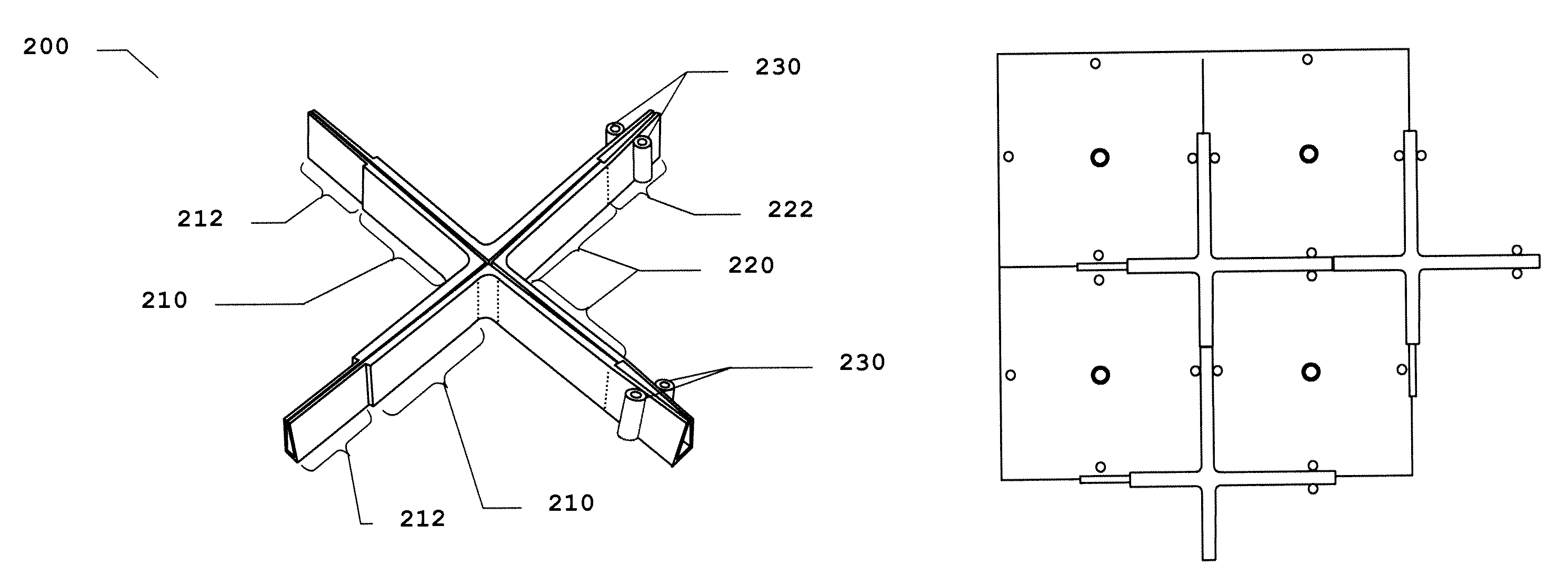
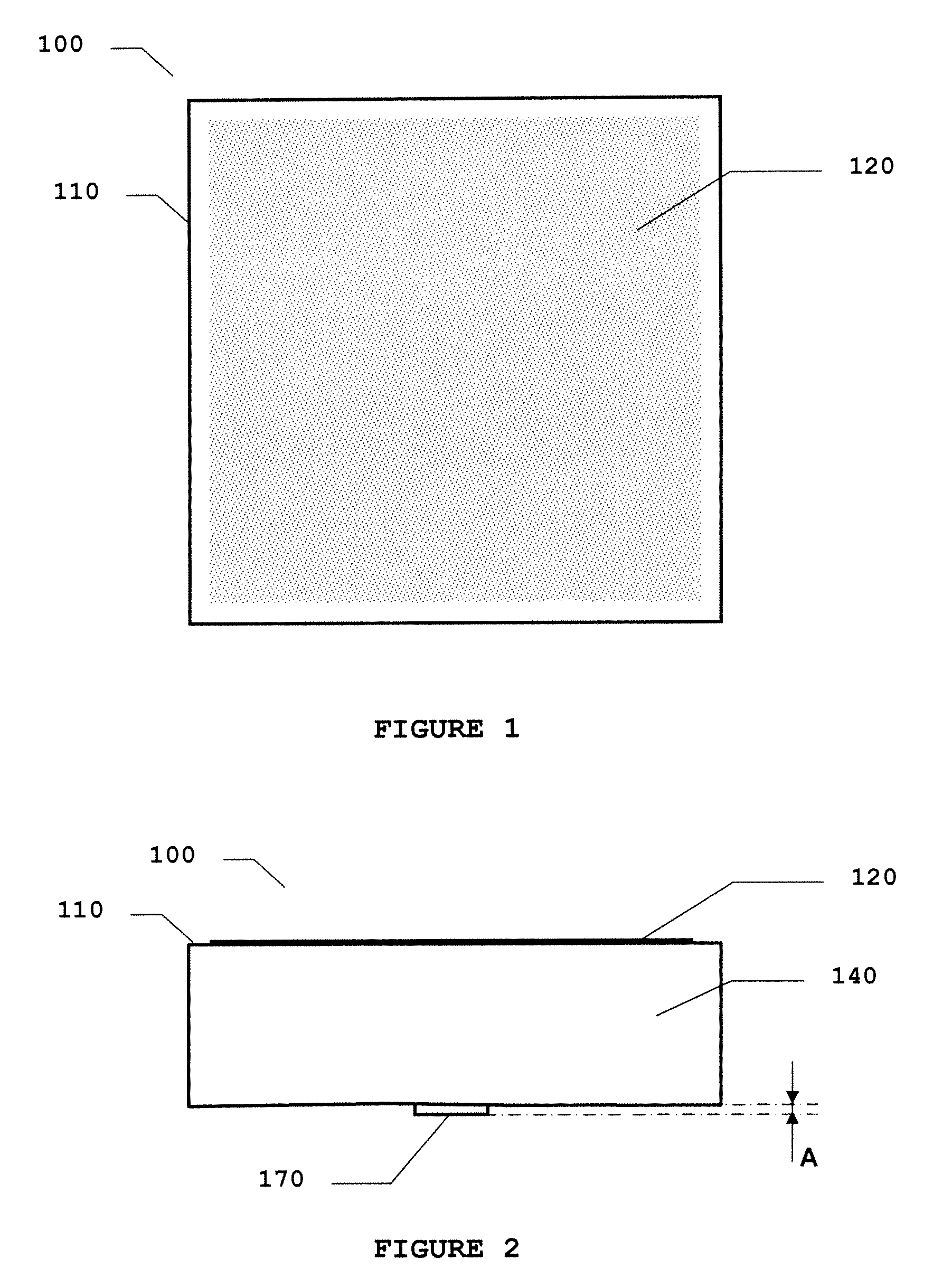
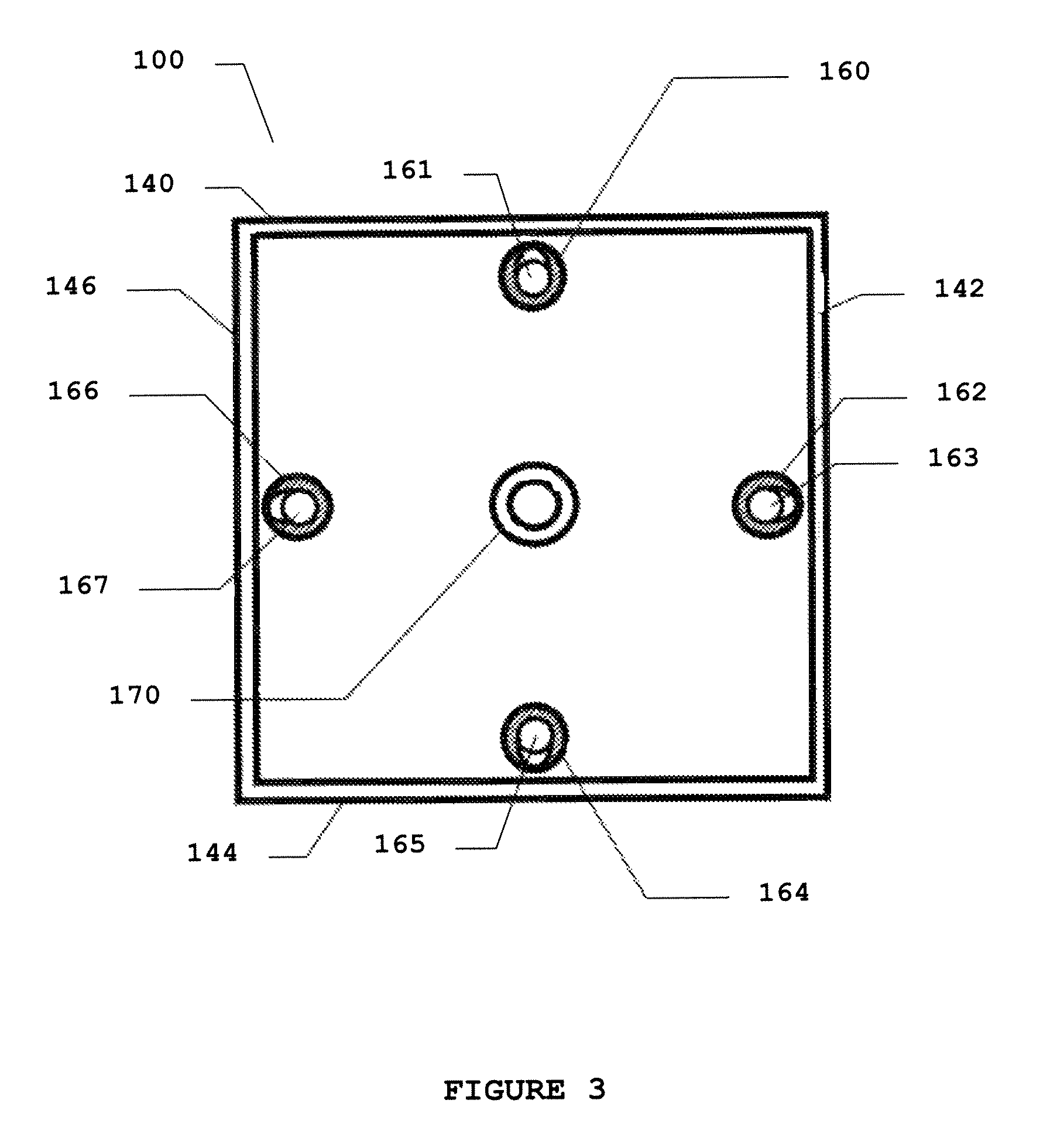
[0022]It must be observed also that the central cylindrical projection of the floor module, has dimensions such that protrude from the plane of the floor module in a measurement that is equivalent to the thickness of the base of the union element, in such way that when several floor modules and union elements are coupled, these central cylindrical projections reach the lower plane of the set of assembled floor and therefore they allow to a strongpoint to the useful surface of each floor module, allowing a great lifting capacity and resistance.

Problems solved by technology

All these references are limited applications in the scope of the construction toys, reason why their dimensions allow that a connection by superposition of minimal areas between blocks is sufficient to maintain the integrity of the connected set.

Method used


Image

  • Assembly system for insulating floors
  • Assembly system for insulating floors
  • Assembly system for insulating floors

Examples


Embodiment Construction

[0042]The following description will be referred to the accompanying drawings before described that must be understood as illustrative of the preferred embodiments of the invention, and non-limiting of the scope of the inventive concept. The common elements in the figures have the same numerical references in all of them.

[0043]The present invention refers to a system that allows the assembling of individual floor modules to form a floor or platform that can be placed on the ground or another floor used as a base, so that a new surface is offered on which a user can freely walk or which can serve as a support base for a load. One of the immediate applications of the invention is in the construction of floors or platforms with electricity insulating properties to allow a person to accede to areas whose conditions, as the conductive water presence or other elements in the ground, could put it in risk of an electrical shock.

[0044]For the accomplishment of the invention, it is considered...


PUM

PropertyMeasurementUnit
diameteraaaaaaaaaa
lengthaaaaaaaaaa
heightaaaaaaaaaa

Abstract

The invention relates to an assembly system used to form insulating floors, in which two types of elements are coupled to one another, namely: hollow prismatic floor modules (100) including one face (110) which forms the load-supporting useful surface and containing cylindrical elements (160, 162, 164, 166) for receiving coupling elements (200); and coupling elements (200) comprising cross-shaped elements with U-sections forming the arms thereof, intended to receive the vertical faces (140, 142, 144, 146) of the floor modules (100), and posts (230) which are coupled to the corresponding hollow cylindrical elements (160, 162, 164, 166) of the floor modules (100) to be joined. The geometric configuration of the modules (100) and the coupling elements (200) ensure that the load on the assembled floor is transmitted to the ground through the vertical walls (140, 142, 144, 146) of the prismatic body (100), the coupling elements (200) and a central cylindrical load body (170). The modules (100) can be made from insulating material and be provided with a non-slip useful surface.

Description

TECHNICAL FIELD[0001]The invention relates to an assembly system used to form insulating floors, designed to be assembled ‘in situ’ directly on the ground or an existing floor, and specially to assemblable floors offering an insulating surface for handling of equipment and electrical systems.BACKGROUND OF THE INVENTION[0002]There are multiple examples in literature related to connectable elements, especially blocks designed to form constructions and double floors, for example. The following are some of them.[0003]The U.S. Pat. No. 6,645,033 (Thomsen, 2003} assigned to Interlego, is an example of the developments by this company in the area of assemblable construction toys, most of which show a similar structure and operation. In this patent, construction elements are described that include a body in the form of box that has a surface with upper and lower sides and a plurality of faces that extend towards underneath this surface, as well as a plurality of projections for connection t...

Claims


Application Information

Patent Timeline
Patent Type & Authority Patents(United States)
IPC IPC(8): E04B5/23E04B5/21
CPCE04F15/02458E04F15/02172E04F15/02194E04F15/105
Inventor GARZA, JOSE LEON
Owner GARZA JOSE LEON
Learn More