Support member for supporting shell, and method

a technology of supporting shells and supporting parts, applied in the field of supporting parts, can solve problems such as no longer being triggered

Inactive Publication Date: 2013-03-05
PATRIA LAND SYST
View PDF11 Cites 4 Cited by
  • Summary
  • Abstract
  • Description
  • Claims
  • Application Information

AI Technical Summary

Benefits of technology

[0014]The invention is based on the idea of locking the shell to the support member by fastening surfaces pressing against each other. An advantage of the invention is that the locking does not require great precision of the dimensioning of the fin or the fastening pieces.
[0015]According to an embodiment of the invention the fastening piece comprises a first arm provided with a first fastening surface and that the first arm is provided with a first spring means, which is arranged to press a fin of a shell arranged to the fastening piece against a second fastening piece, and, as a further option, in that the fastening piece comprises a second arm provided with a second fastening surface and that the second arm is provided with a second spring means arranged to press the a fin of a shell arranged to the fastening piece against the first fastening surface. An advantage in this is that the fastening piece is simple to manufacture, and no tools are required for the fastening.
[0016]According to a second embodiment of the invention the first fastening surface is arranged to a first lever member, which is pivotally fastened in relation to the second fastening surface by a shaft arranged transverse to the longitudinal axis of the shell, that the first lever member is provided with a second lever member arranged on the side of the shaft facing away from the first lever member, that in its released state the lever means tends to pivot so that the first fastening surface moves away from the second fastening surface and that a shell fin to be arranged between the fastening surfaces is arranged to turn the second lever means, whereby the first lever member arranged to the latter turns against the fin of the shell, thus producing a friction locking between the fastening piece and the fin. An advantage in this is that no tools are required for the fastening.
[0017]According to a third embodiment of the invention the first fastening surface is arranged to a first arm fastened to a first flange, the first flange being arranged to a plane transverse to the longitudinal axis of the shell, that the second fastening surface is arranged to a second arm fastened to a second flange, which is arranged parallel and co-axially with the first flange, the flanges rotating in relation to one another in the direction of their planes, and that the support member further comprises means, such as a screw and a wedge surface, for rotating the second flange in relation to the first flange in such a way that the fastening surfaces press against the sides of a fin arranged between them. An advantage in this is that the pressing force is easy to adjust.BRIEF DESCRIPTION OF THE FIGURES
[0018]Some embodiments of the invention will be described in greater detail in the accompanying drawings, in which
[0019]FIG. 1 is a schematic view of a shell supported into a barrel of a weapon by means of a support member according to an

Problems solved by technology

If the mortar is to be fired horizontally or downward, a problem arises from the fact that the shell does not stay in place in the mortar barrel, but may slip forward in the barrel so that it can no longer be triggered.
The solution taught by the publication has the problem that its application requires very exact measurements of both the tail end of the shell and the support member itself to be able to function at least fairly reliably.

Method used


Image

  • Support member for supporting shell, and method
  • Support member for supporting shell, and method
  • Support member for supporting shell, and method

Examples


Embodiment Construction

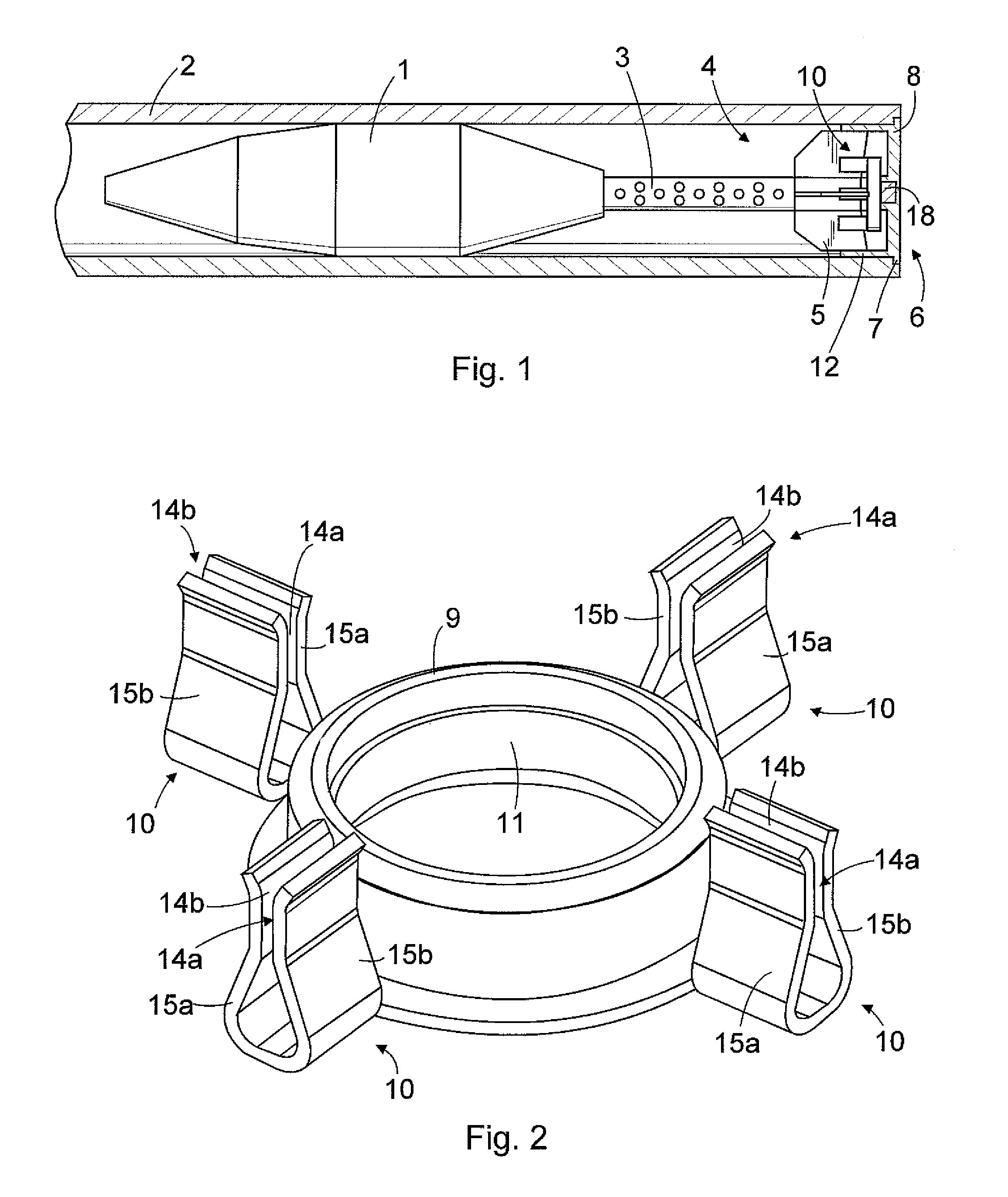
[0029]FIG. 1 is a schematic view of a shell supported into a barrel of a weapon by means of a support member according to an embodiment of the invention.

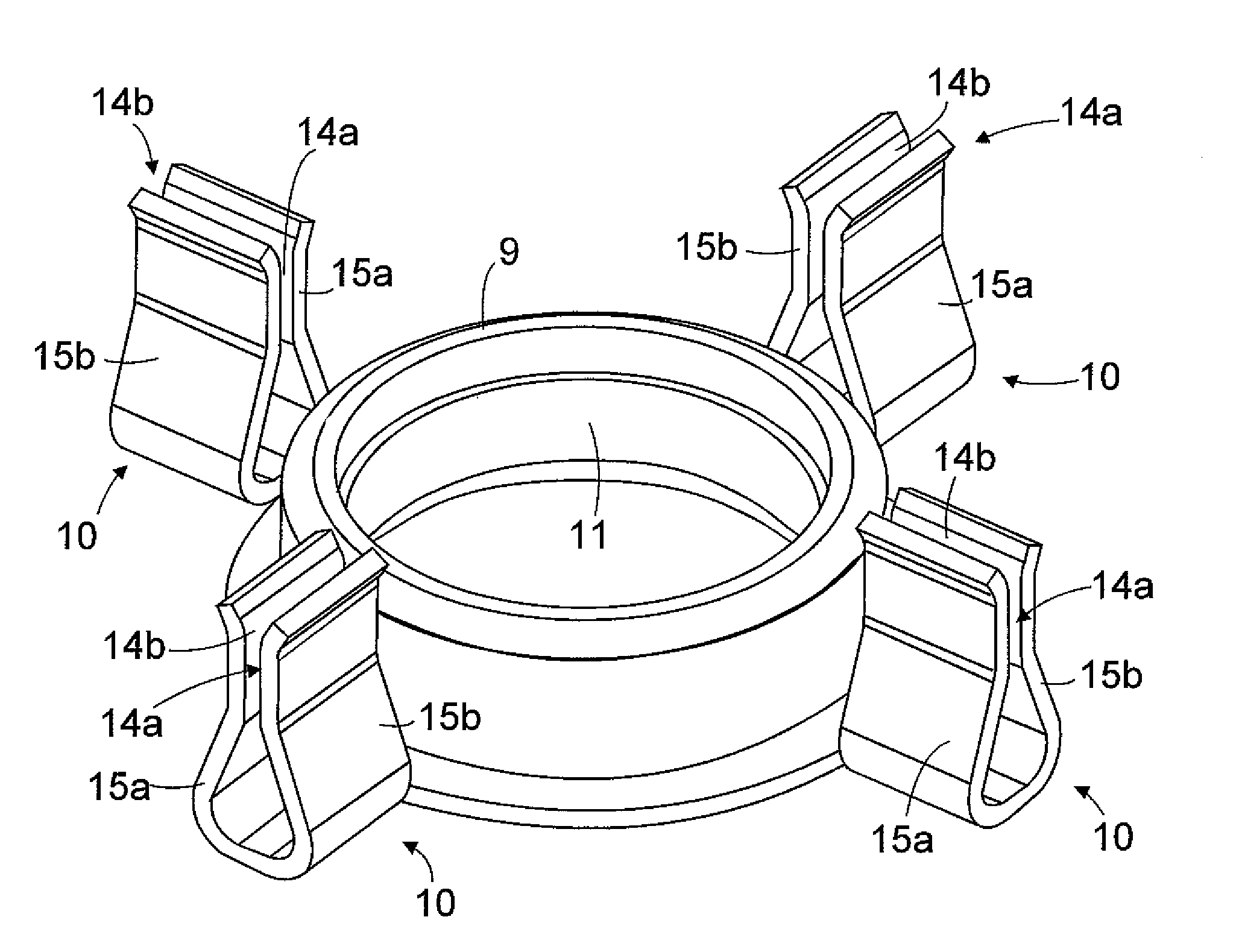
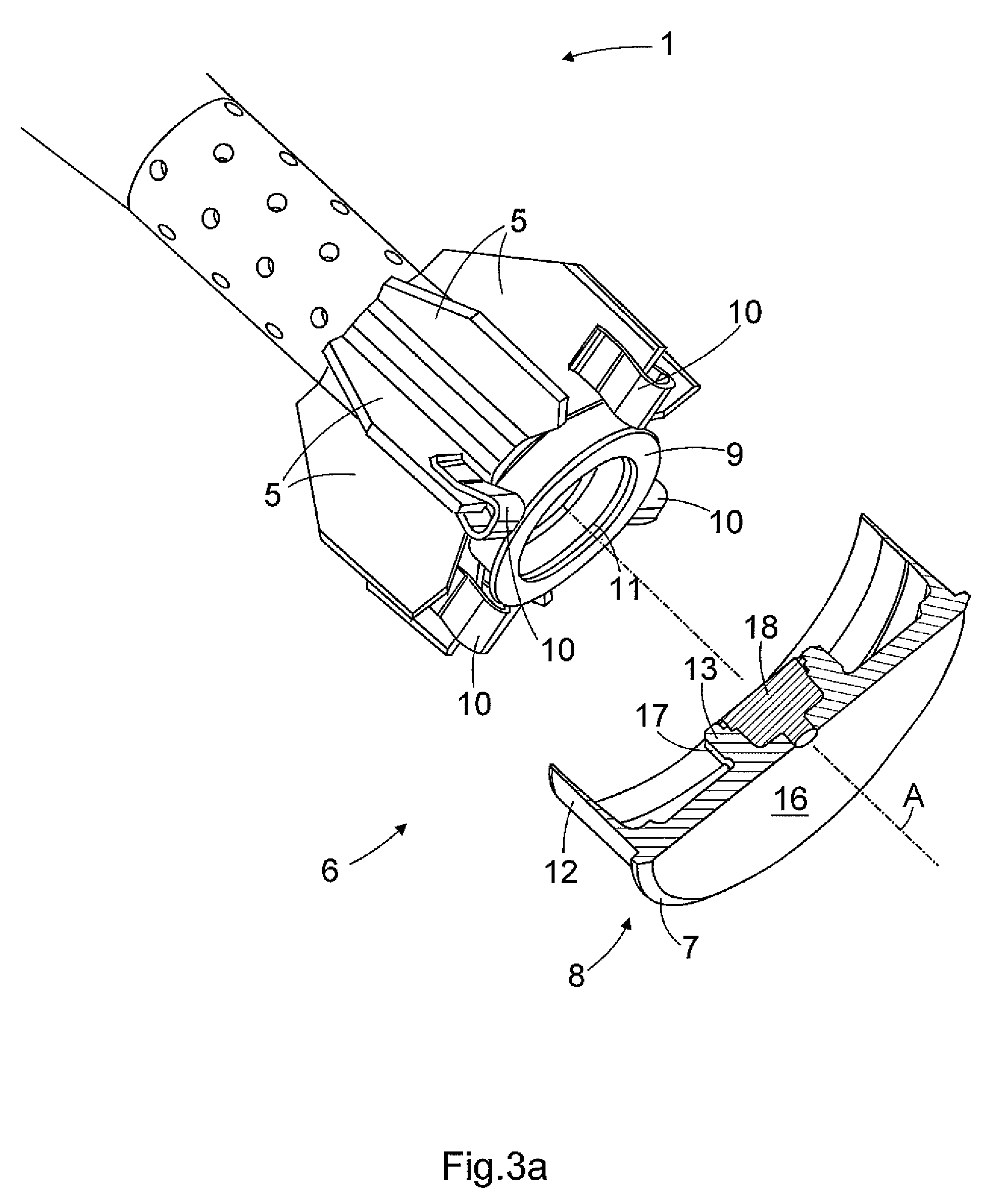
[0030]The shell 1 is arranged into the barrel 2 of a breech-loading weapon. The weapon may be a mortar in which the inner surface of the barrel 2 is essentially smooth. The rear of the shell 1 has a tail pipe 3 and a tail end 4. The tail end 4 comprises one or typically several fins 5 that are used to affect the flight path of the shell 1. The construction of the shell 1 may in detail differ from that shown in the figure. For the sake of clarity, the breech or other details of the weapon are not shown. A support member 6 of the invention is fastened to the tail end 4 so that the shell 1 may be kept in place in the barrel 2 until it is fired. A rim flange 7 on the support member 6 prevents the shell 1 from moving forward in the barrel 2 when the barrel 2 is directed in the horizontal direction or even downward. The support member 6 i...


PUM

PropertyMeasurementUnit
frictionaaaaaaaaaa
forceaaaaaaaaaa
pressing forceaaaaaaaaaa

Abstract

The invention relates to a support member for supporting a shell into the barrel of a breech-loading weapon, and a method. The support member (6) comprises means for fastening a support element (8) to at least one fin (5) belonging to the tail end (4) of a shell (1). The means comprise at least one fastening piece (10), which comprises: at least one first fastening surface (14a), which may be arranged substantially parallel with a side of the fin (5), and which fastening piece (10) may be supported to the support element (8); at least one second fastening surface (14b), which second fastening surface (14b) is movably arranged so that the second fastening surface (14b) is movable in relation to the first fastening surface (14a) in a direction transverse to the longitudinal axis (L) of the shell (1); and means for pressing the fastening surfaces (14a, 14b) against the sides of the fin (5) arranged between them so as to provide friction locking between the fastening piece (10) and the fin (5).

Description

FIELD OF THE INVENTION[0001]The invention relates to a support member for supporting a shell into the barrel of a breech-loading weapon, the support member comprising a support element with a rim flange, and the support member further comprising means for fastening the support element to at least one fin belonging to the tail end of the shell.[0002]The invention further relates to a method for fastening a support member to a shell, the method comprising: fastening to the tail end of the shell a support member that comprises a support element furnished with a rim flange, and locking the support member to at least one fin belonging to the tail end of the shell.BACKGROUND OF THE INVENTION[0003]A mortar may be arranged on a movable platform, such as on an armoured vehicle, whereby the mortar may be easily moved from one location to another, and on the other hand, it may be quickly moved to safety from an emplacement. If the mortar is to be fired horizontally or downward, a problem arise...

Claims


Application Information

Patent Timeline
Patent Type & Authority Patents(United States)
IPC IPC(8): F41F3/04
CPCF41F1/06F41F3/052F41A9/58Y10T29/49826F42B30/10
Inventor NIEMI, PEKKAKAUTTO, JUSSIHAKARI, SEPPO
Owner PATRIA LAND SYST
Why Eureka
Try Eureka