Clamping sleeve

a technology of sleeve and sleeve, which is applied in the field of sleeve, to achieve the effects of reducing manufacturing costs, increasing closing efficiency, and increasing strength and stability

Active Publication Date: 2013-03-05
VEKTEK LLC
View PDF3 Cites 1 Cited by
  • Summary
  • Abstract
  • Description
  • Claims
  • Application Information

AI Technical Summary

Benefits of technology

[0007]Embodiments of the present invention solve the above-mentioned problems and provide a distinct advance in the art of clamping sleeves. More particularly, embodiments of the invention provide a clamping sleeve that includes one or more corrugations using spring-like principles to circumferentially flex the sleeve for increased closing efficiency which in turn allows the clearance between the clamping sleeve and rod to be greater and the clamping sleeve wall to be thicker. Thus, the clamping sleeve is easier to manufacture and possesses greater strength and stability to resist deformation under heavy loads.

Problems solved by technology

Any further increase in the pressure on the tubular sidewall may lead to the clamping sleeve applying a clamping force to an object within the clamping sleeve.

Method used


Image

  • Clamping sleeve
  • Clamping sleeve
  • Clamping sleeve

Examples


Embodiment Construction

[0022]The following detailed description of the invention references the accompanying drawings that illustrate specific embodiments in which the invention can be practiced. The embodiments are intended to describe aspects of the invention in sufficient detail to enable those skilled in the art to practice the invention. Other embodiments can be utilized and changes can be made without departing from the scope of the present invention. The following detailed description is, therefore, not to be taken in a limiting sense. The scope of the present invention is defined only by the appended claims, along with the full scope of equivalents to which such claims are entitled.

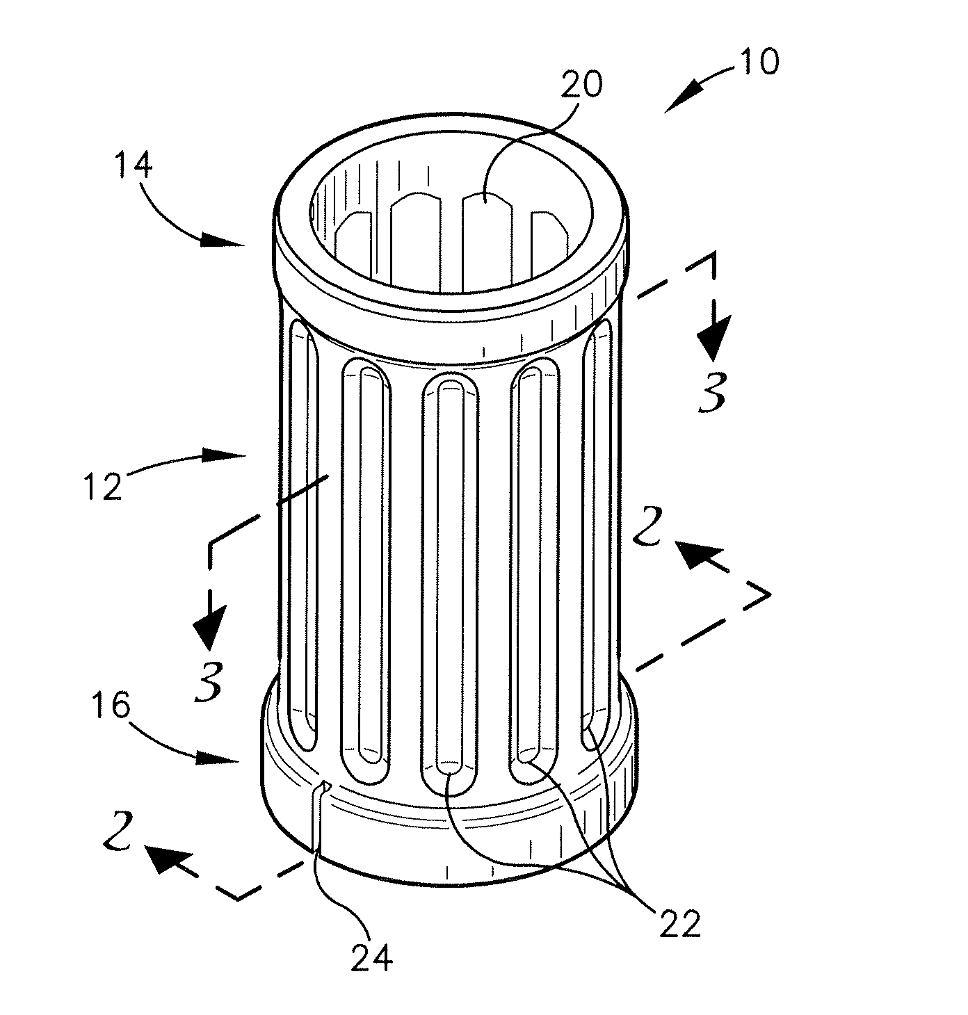
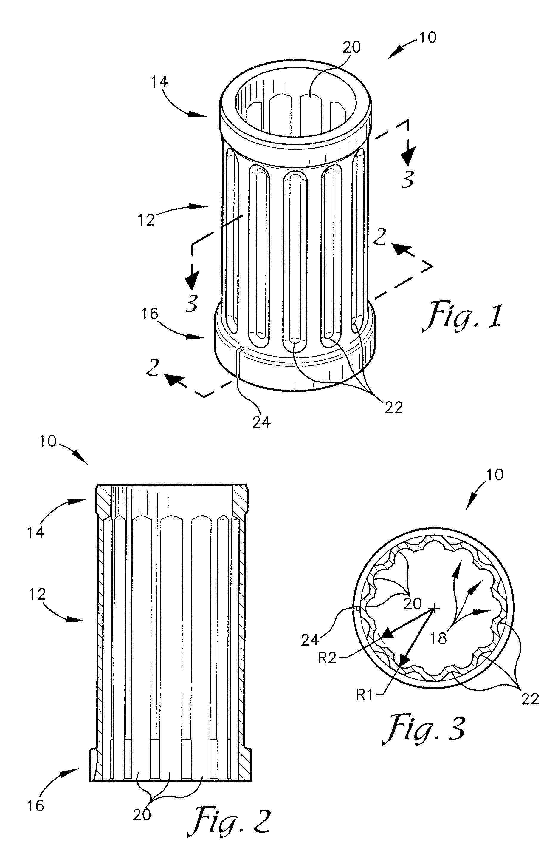
[0023]A clamping sleeve 10, constructed in accordance with various embodiments of the present invention, is shown in FIGS. 1-3. The clamping sleeve 10 is generally monolithic in construction and broadly comprises a tubular sidewall 12, an upper crown 14, and a lower crown 16. The clamping sleeve 10 is generally cylindri...


PUM


Abstract

A clamping sleeve is of generally cylindrical shape with a hollow interior and comprises an upper crown, a lower crown, and a tubular sidewall. The upper crown is positioned at an upper end of the clamping sleeve. The lower crown is positioned at a lower end of the clamping sleeve. The tubular sidewall is positioned between the upper and lower crown and includes one or more corrugations that utilize spring like principles such that pressure applied to the external surface of the tubular sidewall circumferentially flexes the clamping sleeve in order to reduce the diameter of the clamping sleeve and apply a clamping force to an object within the clamping sleeve. The clamping sleeve may be utilized in a work support that includes a plunger positioned within the clamping sleeve, wherein a pressurized flowable medium provides pressure to the exterior of the tubular sidewall thereby causing the clamping sleeve to apply a clamping force to the plunger.

Description

RELATED APPLICATIONS[0001]This nonprovisional patent application claims priority benefit, with regard to all common subject matter, of earlier-filed U.S. provisional patent application titled “CLAMPING SLEEVE”, Ser. No. 61 / 094,284, filed Sep. 4, 2008. The identified earlier-filed application is hereby incorporated by reference in its entirety into the present application.BACKGROUND OF THE INVENTION[0002]1. Field of the Invention[0003]Embodiments of the present invention relate to clamping sleeves. More particularly, embodiments of the present invention relate to clamping sleeves that hold an object in a desired position, preventing axial and rotational movement, while the object is subjected to various loads.[0004]2. Description of the Related Art[0005]Clamping sleeves are generally utilized to hold an object, such as a rod or a plunger, in a desired position while the object is subjected to various loads. Clamping sleeves are utilized in many applications including hydraulic work s...

Claims


Application Information

Patent Timeline
Patent Type & Authority Patents(United States)
IPC IPC(8): B25B1/00
CPCF15B15/262Y10T279/1283
Inventor GRAY, JOSEPHKARRAS, NICK J.
Owner VEKTEK LLC
Why Eureka
Try Eureka