Turbine nozzle assembly including radially-compliant spring member for gas turbine engine

a technology of gas turbine engine and nozzle assembly, which is applied in the direction of machines/engines, liquid fuel engines, lighting and heating apparatus, etc., can solve the problems of relative thermal movement, reduced operational lifespan, and relatively rapid thermomechanical fatigue, and achieve the effect of reducing thermomechanical stress

Inactive Publication Date: 2013-03-05
HONEYWELL INT INC
View PDF31 Cites 26 Cited by
  • Summary
  • Abstract
  • Description
  • Claims
  • Application Information

AI Technical Summary

Benefits of technology

[0006]Embodiments of a turbine nozzle assembly are provided for deployment within a gas turbine engine (GTE) including a first GTE-nozzle mounting interface. In one embodiment, the turbine nozzle assembly includes a turbine nozzle flowbody, a first mounting flange configured to be mounted to the first GTE-nozzle mounting interface, and a first radially-compliant spring member coupled between the turbine nozzle flowbody and the first mounting flange. The turbine nozzle flowbody has an inner nozzle endwall and an outer nozzle endwall, which is fixedly coupled to the inner nozzle endwall and which cooperates therewith to define a flow passage through the turbine nozzle flowbody. The first radially-compliant spring member accommodates relative thermal movement between the turbine nozzle flowbody and the first mounting flange to alleviate thermomechanical stress during operation of the GTE.

Problems solved by technology

Significant temperature gradients thus occur within the GTE during operation, which result in relative thermal movement (also referred to as “thermal distortion”) between the HPT nozzle, the GTE-nozzle mounting interfaces, and the trailing end of the combustor.
Due to their inherent rigidity, conventional HPT nozzles of the type described above are often unable to adequately accommodate such thermal distortion and, as a result, can experience relatively rapid thermomechanical fatigue and reduced operational lifespan.
In addition, thermal distortion between the HPT nozzle, the combustor end, and the GTE-nozzle mounting interfaces can result in the formation of leakage paths, even if such mating components fit closely in a non-distorted, pre-combustion state.
However, the sealing characteristics of the compression seals can be compromised when the nozzle mounting flanges, and specifically when the mounting flange sealing surfaces contacting the compression seals, are heated to elevated temperatures by combustive gas flow through the turbine nozzle flowbody.
Although the radial height of the mounting flanges can be increased to further thermally isolate the flange sealing surfaces from the combustive gas flow, increasing the height of the radial mounting flanges undesirably increases the overall envelope of the HPT nozzle and consumes a greater volume of the limited space available within the engine casing.

Method used


Image

  • Turbine nozzle assembly including radially-compliant spring member for gas turbine engine
  • Turbine nozzle assembly including radially-compliant spring member for gas turbine engine
  • Turbine nozzle assembly including radially-compliant spring member for gas turbine engine

Examples


Embodiment Construction

[0013]The following Detailed Description is merely exemplary in nature and is not intended to limit the invention or the application and uses of the invention. Furthermore, there is no intention to be bound by any theory presented in the preceding Background or the following Detailed Description.

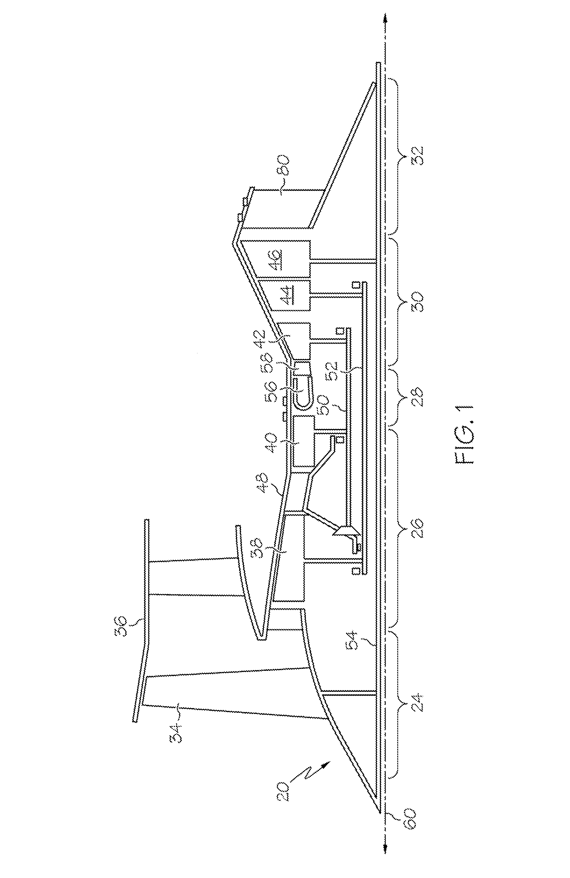
[0014]FIG. 1 is a generalized cross-sectional view of the upper portion of an exemplary gas turbine engine (GTE) 20. In the exemplary embodiment illustrated in FIG. 1, GTE 20 assumes the form of a three spool turbofan engine including an intake section 24, a compressor section 26, a combustion section 28, a turbine section 30, and an exhaust section 32. Intake section 24 includes a fan 34, which may be mounted within an outer fan case 36. Compressor section 26 includes an intermediate pressure (IP) compressor 38 and a high pressure (HP) compressor 40; and turbine section 30 includes an HP turbine 42, an IP turbine 44, and a low pressure (LP) turbine 46. IP compressor 38, HP compressor 40, HP...


PUM


Abstract

Embodiments of a turbine nozzle assembly are provided for deployment within a gas turbine engine (GTE) including a first GTE-nozzle mounting interface. In one embodiment, the turbine nozzle assembly includes a turbine nozzle flowbody, a first mounting flange configured to be mounted to the first GTE-nozzle mounting interface, and a first radially-compliant spring member coupled between the turbine nozzle flowbody and the first mounting flange. The turbine nozzle flowbody has an inner nozzle endwall and an outer nozzle endwall, which is fixedly coupled to the inner nozzle endwall and which cooperates therewith to define a flow passage through the turbine nozzle flowbody. The first radially-compliant spring member accommodates relative thermal movement between the turbine nozzle flowbody and the first mounting flange to alleviate thermomechanical stress during operation of the GTE.

Description

STATEMENT REGARDING FEDERALLY SPONSORED RESEARCH OR DEVELOPMENT[0001]This invention was made with Government support under Contract No. W911W6-08-2-0001 awarded by the Department of Defense. The Government has certain rights in this invention.TECHNICAL FIELD[0002]The present invention relates generally to gas turbine engines and, more particularly, to embodiments of a turbine nozzle assembly having at least one radially-compliant spring member.BACKGROUND[0003]In one well-known type of gas turbine engine (GTE), at least one high pressure turbine (HPT) nozzle is mounted within an engine casing between a combustor and a high pressure (HP) air turbine. In single nozzle GTE platforms, the HPT nozzle typically includes an annular nozzle flowbody having an inner nozzle endwall and an outer nozzle endwall, which circumscribes the inner nozzle endwall. A plurality of circumferentially spaced stator vanes extends between the outer and inner nozzle endwalls and cooperates therewith to define a...

Claims


Application Information

Patent Timeline
Patent Type & Authority Patents(United States)
IPC IPC(8): F01D25/24
CPCF01D9/02F01D9/042F05D2260/38F05D2260/941
Inventor SMOKE, JASONKUJALA, STONYWOODCOCK, GREGORY O.TUCKER, BRADLEY REED
Owner HONEYWELL INT INC
Why Eureka
Try Eureka