Support orthopaedic device for a knee joint

a technology for supporting orthopaedic devices and knee joints, which is applied in invalid friendly devices, medical science, surgery, etc., can solve the problems of difficult to reproduce kinematics with a reliable and small-sized mechanism, the articulation between the orthopaedic devices, and the inability to ensure functional conditions, etc., to achieve convenient positioning and modular assembly, fast and precise implant

Active Publication Date: 2013-03-05
ORTHOFIX SRL
View PDF8 Cites 7 Cited by
  • Summary
  • Abstract
  • Description
  • Claims
  • Application Information

AI Technical Summary

Benefits of technology

[0013]An advantage of the invention is the fact that the device according to the present invention is easily positioned and modularly assembled with other known orthopaedic devices, ensuring a fast and precise implant.

Problems solved by technology

The unloading of the joint may be obtained by total immobilization of the knee; on the other hand, this solution has substantial therapeutic drawbacks, and is therefore not often used.
A primary drawback of known orthopaedic devices is the articulation between the two connectors.
Such functional conditions are not ensured by simple and efficient constructive morphology.
In fact, the coupling provided by the knee joint foresees a combination of rotations and relative slipping among the two affected bones, whose kinematics are difficult to reproduce with a reliable and small-sized mechanism.
In fact, such a coupling cannot be reproduced by a simple hinge having a fixed rotational axis.
A second problem arising from the therapeutic use of orthopaedic devices according to the known art is the precise positioning of the same device with respect to the bone structure of the patient.
Moreover, the attachment sites are relatively remote from the joint compartment, further complicating the problem regarding a proper positioning of the orthopaedic device.

Method used


Image

  • Support orthopaedic device for a knee joint
  • Support orthopaedic device for a knee joint
  • Support orthopaedic device for a knee joint

Examples


Embodiment Construction

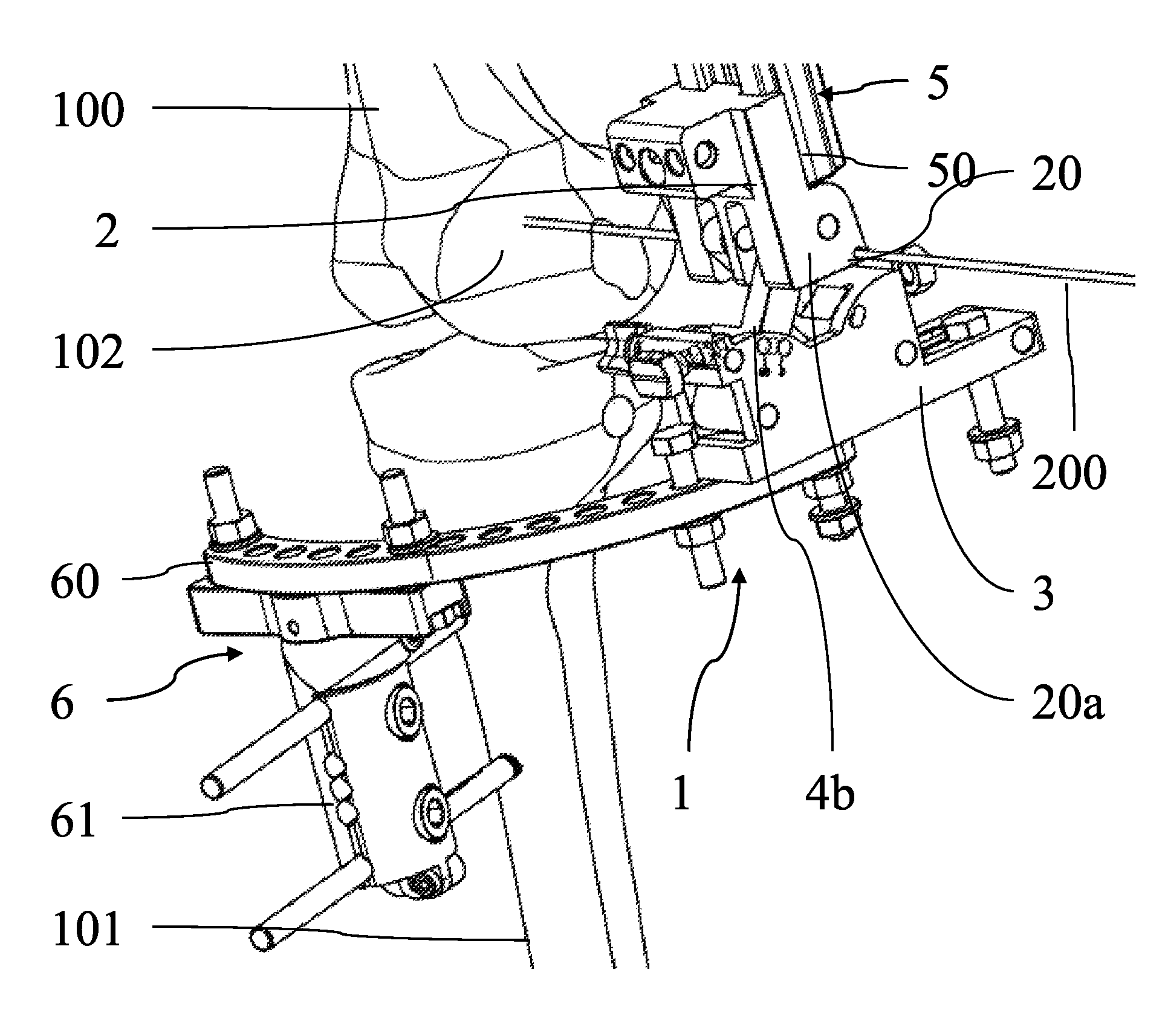
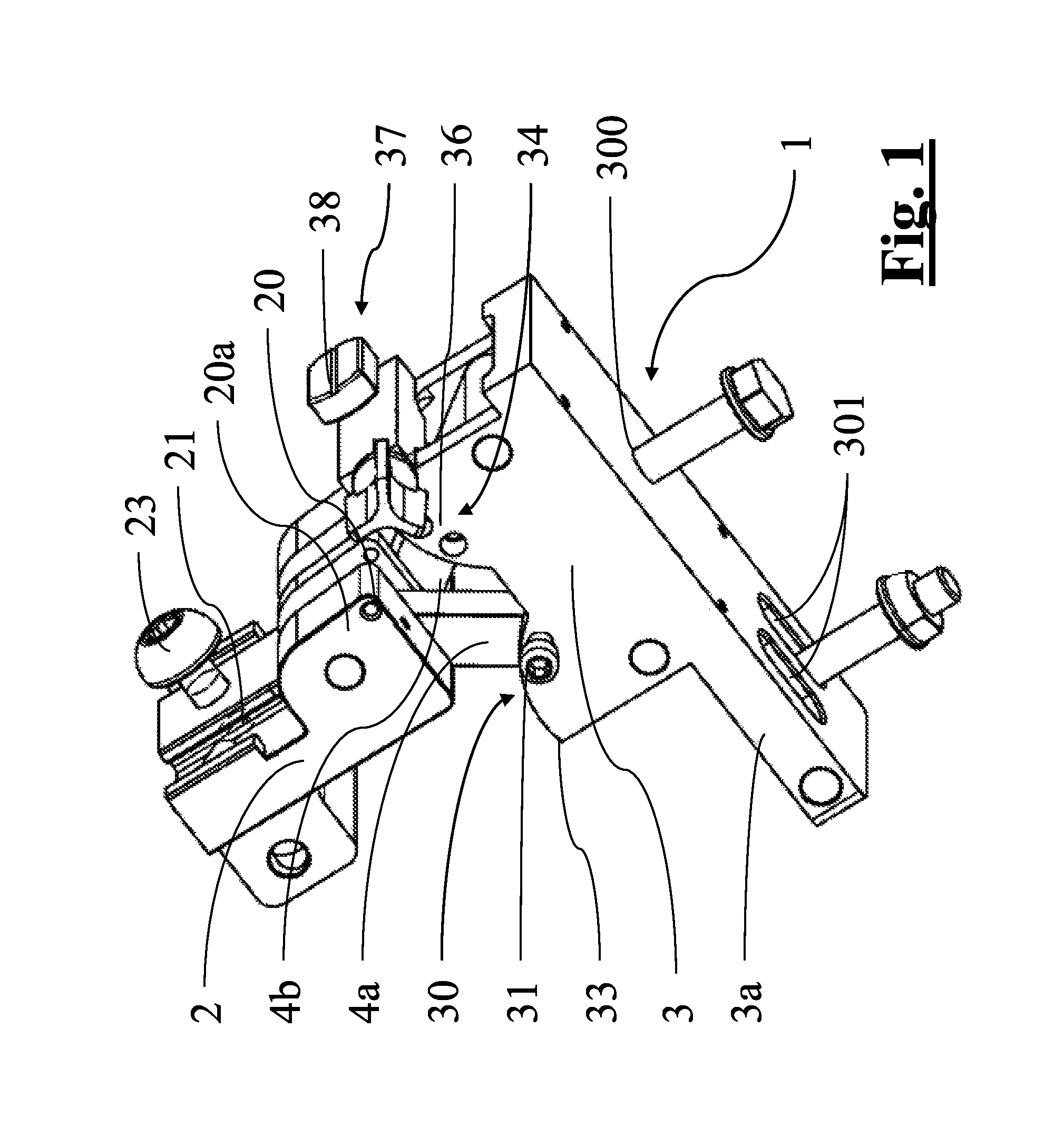
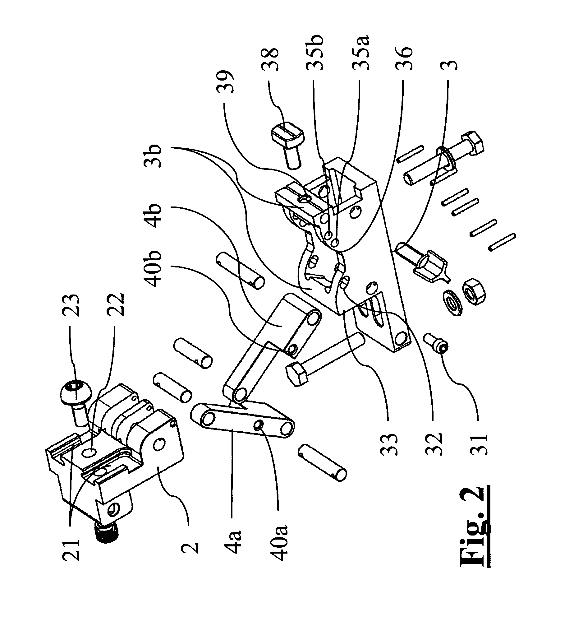
[0022]With reference to the appended figures, reference numeral 1 indicates a support orthopaedic device for a knee joint. The primary task of such a device, as already said, is to transmit the same loads that would otherwise act on the joint, allowing for proper healing during the post-surgery period and at the same time ensuring an at least partial mobility of the affected lower limb.

[0023]The orthopaedic device 1 comprises a proximal connector 2 and a distal connector 3, which are articulated to each other and are provided to be respectively associated to a proximal bone 100 and distal bone 101 of a lower limb, which are connected to each other by means of the knee joint. In particular, in the preferred embodiment of the appended figures the proximal bone 100 is the femur of the patient, whereas the distal bone 101 is advantageously the tibia.

[0024]Said orthopaedic device 1 also comprises a first rod 4a and a second rod 4b, said rods 4a, 4b being hinged, along hinging axes that a...


PUM


Abstract

Support orthopaedic device (1) for a knee joint, comprising a proximal connector (2) and a distal connector (3), articulated among themselves and respectively intended to be associated with a proximal bone (100) and a distal bone (101) of a lower limb connected among themselves by a knee joint. The device comprises a first rod (4a) and a second rod (4b), which are hinged, according to hinging axes normal to a median excursion plane of the orthopaedic device (1), to the proximal connector (2) and to the distal connector (3) so as to form with them an articulated quadrilateral. The articulated quadrilateral is planarly mobile according to a plane parallel to the excursion plane between a configuration corresponding to an extended position of the knee joint and configurations corresponding to bendings of different entity of the knee joint; the relative motion imposed to the proximal and distal connectors (2, 3) by the articulated quadrilateral is consistent with the physiological movement of the knee joint.

Description

CROSS-REFERENCE TO RELATED APPLICATIONS[0001]This application is a §371 national stage entry of International Application No. PCT / IB2009 / 006795, filed Sep. 10, 2009, which claims priority to Italian Application No. BO2008A000549, filed Sep. 11, 2008, both of which are hereby incorporated herein by reference in their entirety.FIELD OF APPLICATION[0002]The present invention relates to a support orthopaedic device for a knee joint.[0003]In particular, the device is of the type comprising a proximal connector and a distal connector, articulated to each other and intended to be respectively associated to a femoral bone and to a tibial bone of the lower limb of a patient, these bones being connected to each other through a knee joint.PRIOR ART[0004]Knee joint compartments may be subject to surgical operations for trauma or corrective treatment. Such operations, as in the general case of any orthopaedic operation, are characterized by a post-operational period in which the ossification pro...

Claims


Application Information

Patent Timeline
Patent Type & Authority Patents(United States)
IPC IPC(8): A61B17/56
CPCA61B17/62A61B17/6425A61B2090/034
Inventor BAGNASCO, MARAVENTURINI, DANIELEMARINI, GRAZIANO
Owner ORTHOFIX SRL
Why Eureka
Try Eureka