Method of particle trajectory recognition in particle flows of high particle concentration using a candidate trajectory tree process with variable search areas

Inactive Publication Date: 2013-03-05
THE UNITED STATES AS REPRESENTED BY THE DEPARTMENT OF ENERGY
View PDF7 Cites 4 Cited by
  • Summary
  • Abstract
  • Description
  • Claims
  • Application Information

AI Technical Summary

Benefits of technology

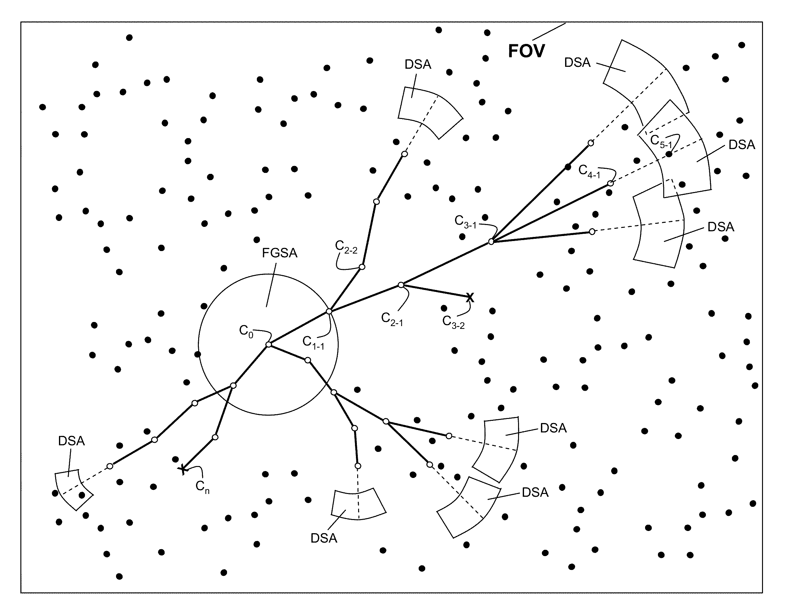
[0015]This method disclosed recognizes trajectories in a Centroid Population. In an embodiment, the trajectories are trajectories of particles in particle flows of high particle concentration. In high concentration flows a high percentage of particle trajectories cross each other over successive camera frames, and particle images are missing because of image overlap or image shadowing, either on the same frame or on successive frames. The high concentration particle flow may be recorded on a standard or high speed video, an

Problems solved by technology

The difficulty, complexity, and computer time required to automatically recognize particle trajectories increases exponentially with concentration of particles (number of particles per unit area on the camera frames).
With low particle concentrations, the particle concentration is not high enough to occlude optical access for the camera view or to block illumination.
However, particle flows of high concentration present a number of problems not found in low concentrations: optical access is almost completely occluded, almost all particle trajectories cross other trajectories, a high percentage of particle images overlap (either on the same frame or across frames), and some particles are not illuminated because they are in the shadow of other particles.
Trajector

Method used


Image

  • Method of particle trajectory recognition in particle flows of high particle concentration using a candidate trajectory tree process with variable search areas
  • Method of particle trajectory recognition in particle flows of high particle concentration using a candidate trajectory tree process with variable search areas
  • Method of particle trajectory recognition in particle flows of high particle concentration using a candidate trajectory tree process with variable search areas

Examples


Example

[0036]The following description is provided to enable any person skilled in the art to use the method disclosed herein and sets forth the best mode contemplated by the inventor for carrying out the method. Various modifications, however, will remain readily apparent to those skilled in the art, since the principles of the present method are disclosed herein specifically to provide a method of particle image trajectory recognition in series of camera frames of particle flows with high particle concentrations.

[0037]Within the method, particle trajectory recognition may be based on priori knowledge of particle flow behavior, but the initial size, location, and shape of search areas in successive frames are severely limited. The limitation is achieved by basing the size, location, and shape of search areas on particle flow properties, namely particle velocity and acceleration.

[0038]Within the method, trajectories are realized for centroids in a centroid population. In one embodiment, th...


PUM


Abstract

The application relates to particle trajectory recognition from a Centroid Population comprised of Centroids having an (x, y, t) or (x, y, f) coordinate. The method is applicable to visualization and measurement of particle flow fields of high particle. In one embodiment, the centroids are generated from particle images recorded on camera frames. The application encompasses digital computer systems and distribution mediums implementing the method disclosed and is particularly applicable to recognizing trajectories of particles in particle flows of high particle concentration. The method accomplishes trajectory recognition by forming Candidate Trajectory Trees and repeated searches at varying Search Velocities, such that initial search areas are set to a minimum size in order to recognize only the slowest, least accelerating particles which produce higher local concentrations. When a trajectory is recognized, the centroids in that trajectory are removed from consideration in future searches.

Description

STATEMENT OF GOVERNMENTAL SUPPORT[0001]The United States Government has rights in this invention pursuant to the employer-employee relationship of the Government to the inventors as U.S. Department of Energy employees and site-support contractors at the National Energy Technology Laboratory.FIELD OF THE INVENTION[0002]The application relates to particle trajectory recognition from a Centroid Population comprised of Centroids having an (x, y, t) or (x, y, f) coordinate. The method is applicable to visualization of high concentration particle flow fields. In one embodiment, the centroids are generated from video particle images. The application encompasses digital computer systems and distribution mediums implementing the method disclosed.BACKGROUND OF THE INVENTION[0003]The motion of flowing particles is often visualized and measured by recording a particle flow field with a standard or high speed camera. The recorded video is transferred to a computer, then particle images on the vi...

Claims


Application Information

Patent Timeline
IPC IPC(8): G06K9/00
CPCG01P5/20G01P5/001
Inventor SHAFFER, FRANKLIN D.
Owner THE UNITED STATES AS REPRESENTED BY THE DEPARTMENT OF ENERGY
Why Eureka
Try Eureka