Box service panel door and equalizer

a technology of box service panel and equalizer, which is applied in the direction of engine components, coast protection, mechanical apparatus, etc., can solve the problems of reducing the effectiveness and efficiency of the service procedure, affecting the service life of the box, so as to prevent the water from prematurely leaking and easy to remove

Inactive Publication Date: 2013-03-12
OLDCASTLE INFRASTRUCTURE INC
View PDF18 Cites 17 Cited by
  • Summary
  • Abstract
  • Description
  • Claims
  • Application Information

AI Technical Summary

Benefits of technology

[0012]The damper panel is typically made of metal, fiberglass, or plastic, combinations thereof, and the like, can have a cam system mechanism along the vertical edges of the panel on one side. On the other side of the panel a rubber seal is continuous along the edge of the panel, going down one side, then across the bottom, and then up the other side. When the damper panel is lowered into the track system to block the pipe it is very loose and does not bind along the track system. When the cams are rotated the mechanism can then force the panel to wedge into the track and compress the rubber seal along the inside surface of the track. Once the cams have wedged the damper panel in place and the rubber seal is compressed against the track, the panel is locked in place and it will not leak water from the pipe into the stommwater vault.
[0013]The cams can be rotated to either lock the damper panel in place or release the damper panel. The cams can be either rotated by a lever attached to the top of the cam system, or a wrench, or other tools such as but not limited to pliers, pipes, and the like. The wrench can be either hand held or socket attached to the end of a hand held pole. The advantage of attaching the socket to the end of a long pole is that a person does not need to enter the vault to rotate the cams.
[0014]The damper panel can have a special lifting point attachment that allows the panel to be lowered into the track system without having to enter the vault. The lifting point would have a slot that would sized to receive an approximately 1″ diameter ball such as a metal sphere attached to

Problems solved by technology

However, over time stormwater treatment systems often will fill with collected debris and will require service to remove the collected debris.
However, servicing stormwater structures is often complicated by unwanted water flow running into the stormwater structures during the service procedure.
This unwanted water flow typically originates from high water levels in lakes and rivers adjacent to the t

Method used


Image

  • Box service panel door and equalizer
  • Box service panel door and equalizer
  • Box service panel door and equalizer

Examples


Embodiment Construction

[0066]Before explaining the disclosed embodiments of the present invention in detail it is to be understood that the invention is not limited in its applications to the details of the particular arrangements shown since the invention is capable of other embodiments. Also, the terminology used herein is for the purpose of description and not of limitation.

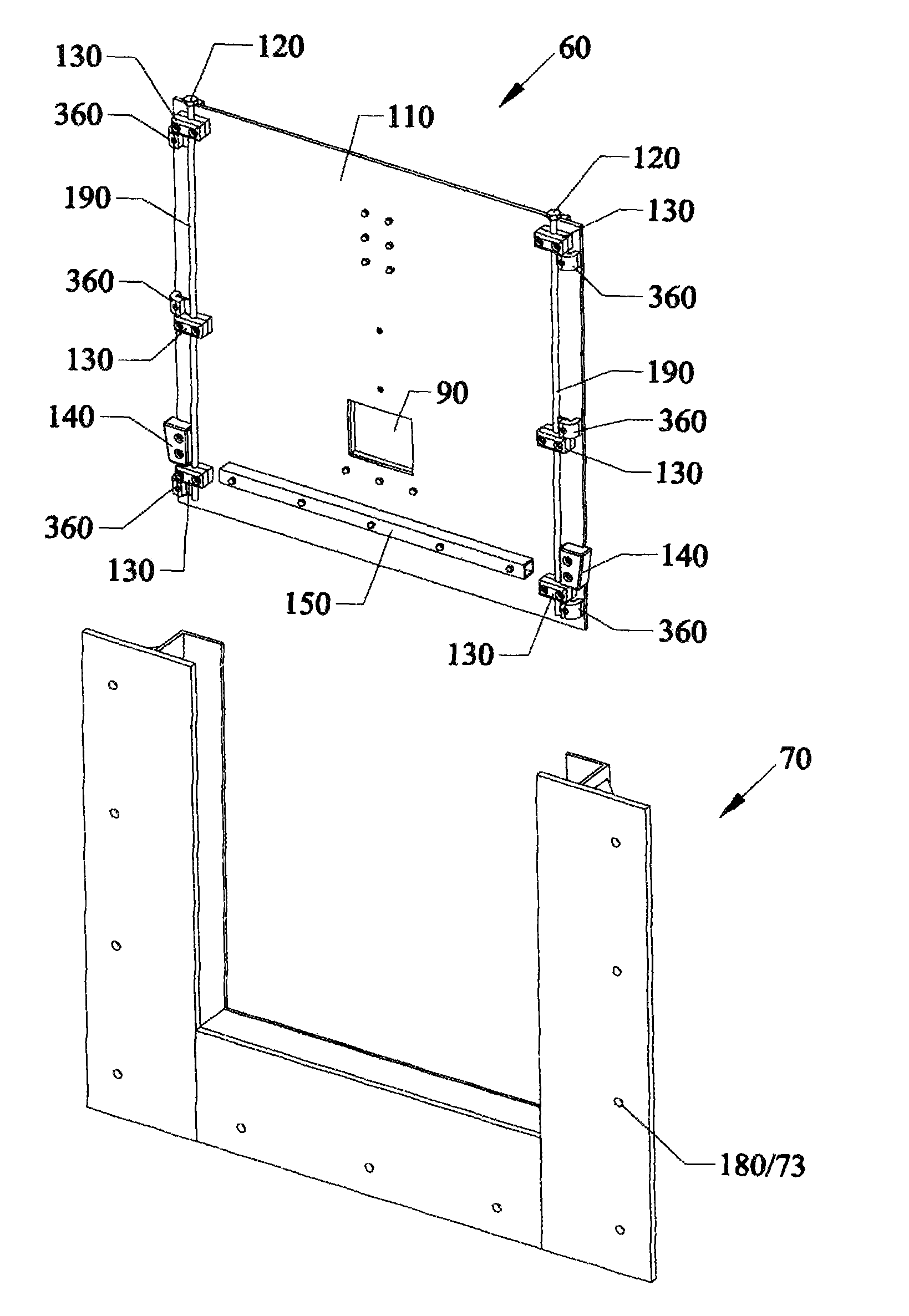
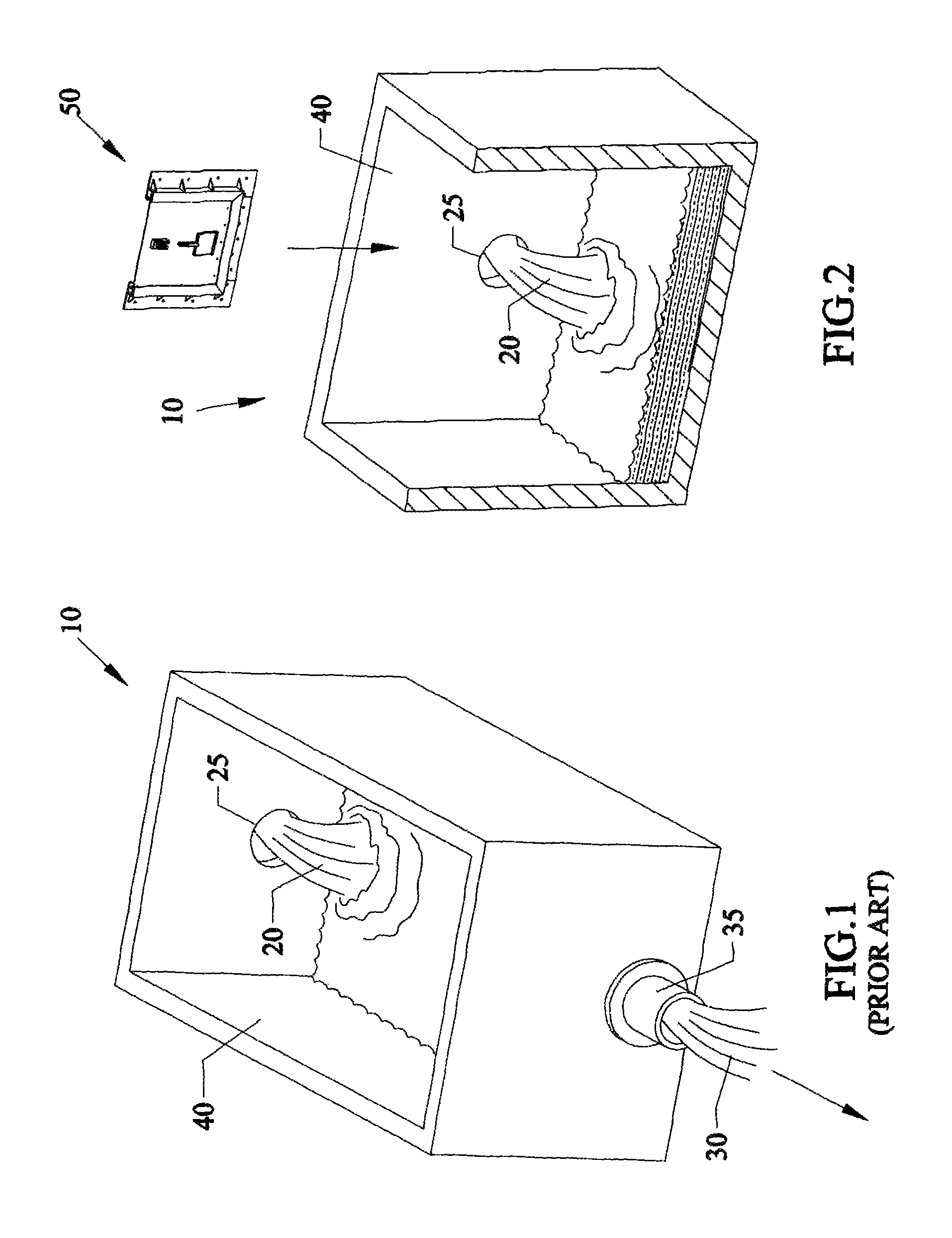
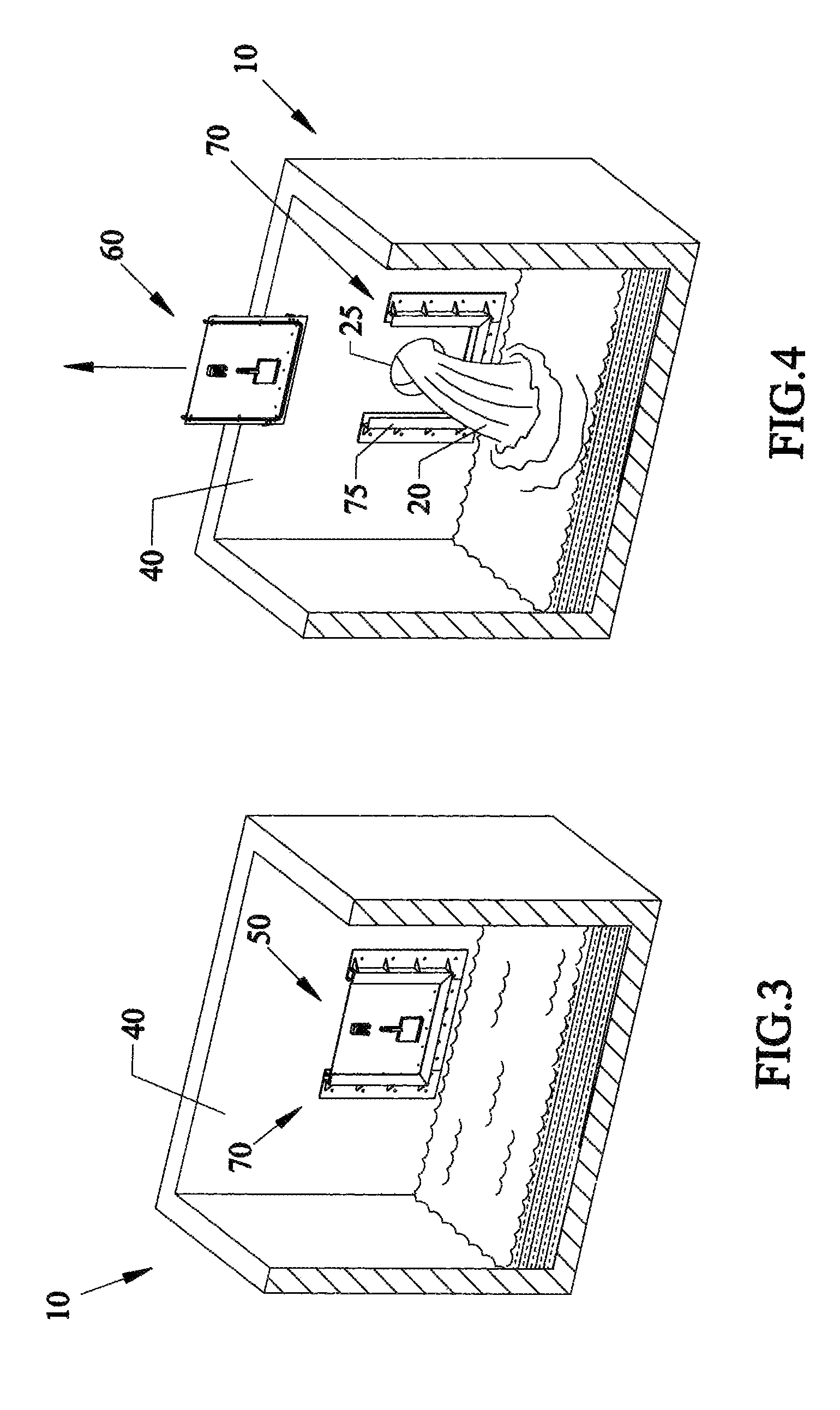
[0067]A list of components will now be described.[0068]10. Concrete storm water handling vault.[0069]20. Storm water inflow.[0070]25. Inlet port[0071]30. Storm water outflow.[0072]35. Outlet pipe[0073]40. Vault wall.[0074]50. Damper system.[0075]60. Damper panel assembly.[0076]70. Damper frame assembly.[0077]71. Through-holes for fasteners[0078]72. U-shaped plates[0079]75. Parallel tracks in frame assembly[0080]76. angled support plates[0081]77. Lower channel for damper panel[0082]78. Inner lip of frame[0083]79. Another lip of frame[0084]80. Panel lifting cleat.[0085]90. Pressure relief door.[0086]95. opening in panel[0087]100. Pres...


PUM


Abstract

Systems, devices, apparatus, and methods of locking and unlocking a door that is slidable through tracks, over an entry port to a storm water type vault or storm water structure. Locking the door in place can be accomplished by rotating upwardly protruding bolt type heads that are fixably attached to cams. Rotating the bolt type heads causes the cams to press the door against one side of the tracks. An elongated sealing strip can be compressed between the door edges and the one side of the track and seal and prevent water from passing about the sides of the door. Alternatively, removable wedges can be used to compress door edges in place. Furthermore, a hinged pressure relief door can be attached over a small opening in the slidable door. Opening the small pressure relief door by an elongated tool allows for water on both sides of the sliding door to equalize. Once water has equalized on both sides the tool can be used to rotate the bolt type heads on the top of the slidable door and make it easier to next pull the sliding door from the tracks. The vault/structure can be sealed so that a vacuum truck can then remove water and debris contents inside of the vault/structure at the beginning of the treatment service.

Description

[0001]This invention relates to stormwater treatment, in particular to devices, apparatus, systems and methods of using a damper system to isolate a stormwater treatment structure from unwanted water inflow during servicing so that a vacuum such as vacuum truck deals with the contents of the treatment structure at the beginning of the service, where a slidable door can be sealed in place with rotatable cams pushing one side of the door against portions of the tracks, and a small pressure relief door can be used in the sliding door to allow for water pressure to equalize on both sides of the sliding door, or alternatively using removable triangular wedges to jam the door in place.BACKGROUND AND PRIOR ART[0002]There are federal clean water requirements that require water bodies such as lakes and rivers must meet strict minimal water quality specifications. To achieve these requirements, stormwater drainage pipes often require treatment before conveying stormwater into receiving water ...

Claims


Application Information

Patent Timeline
IPC IPC(8): E02B7/28
CPCE03F5/105
Inventor HAPPEL, TOM
Owner OLDCASTLE INFRASTRUCTURE INC
Why Eureka
Try Eureka