Card seal for a turbine

Inactive Publication Date: 2013-03-12
FLORIDA TURBINE TECH
View PDF4 Cites 14 Cited by
  • Summary
  • Abstract
  • Description
  • Claims
  • Application Information

AI Technical Summary

Benefits of technology

[0014]It is an object of the present invention to provide for a card seal wi

Problems solved by technology

As higher rotational speeds, the brushes will wear out early.
Brush seals have less leakage than labyrinth seals, but wear out easily when rubbing at higher speeds

Method used


Image

  • Card seal for a turbine
  • Card seal for a turbine

Examples


Example

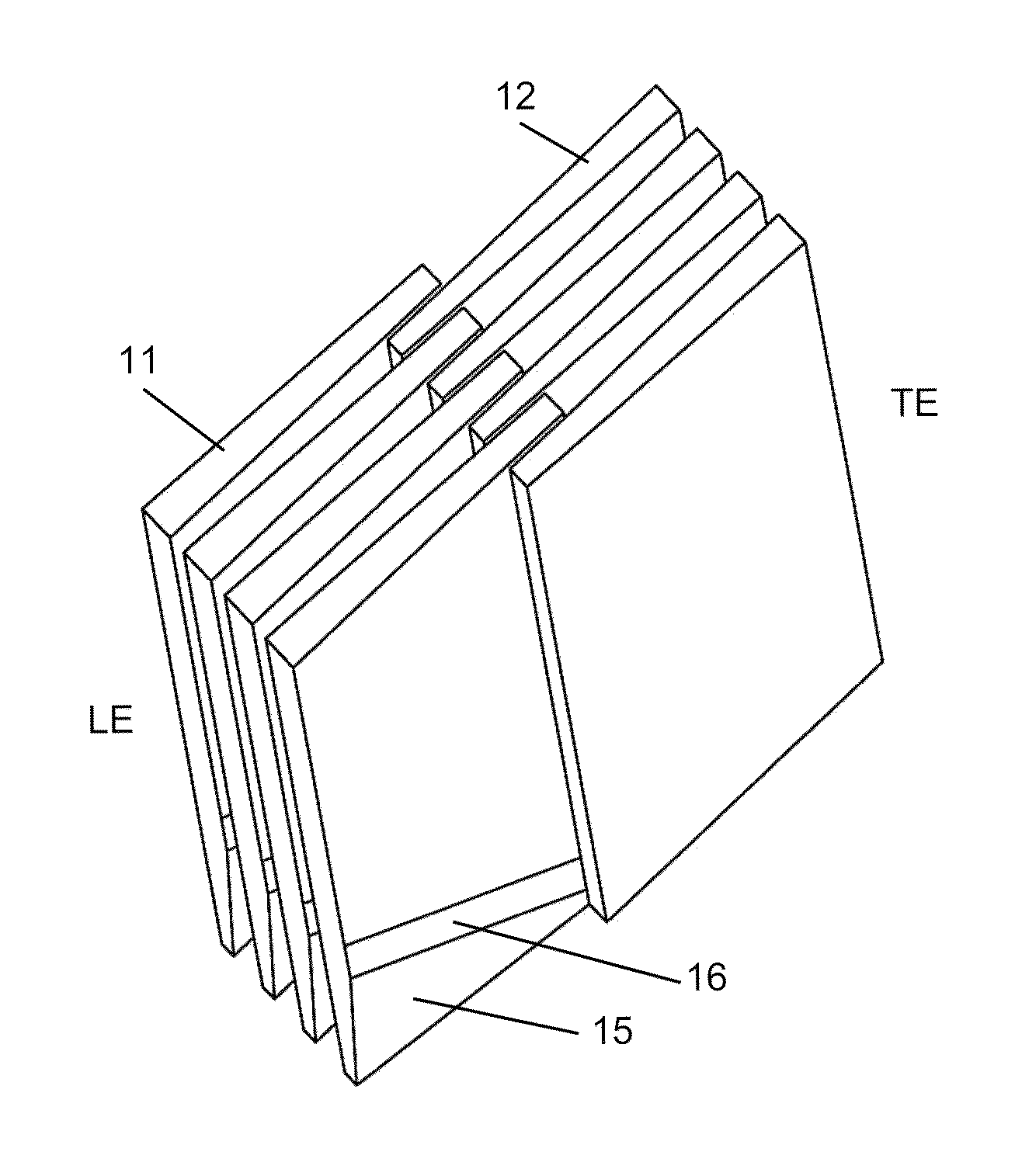
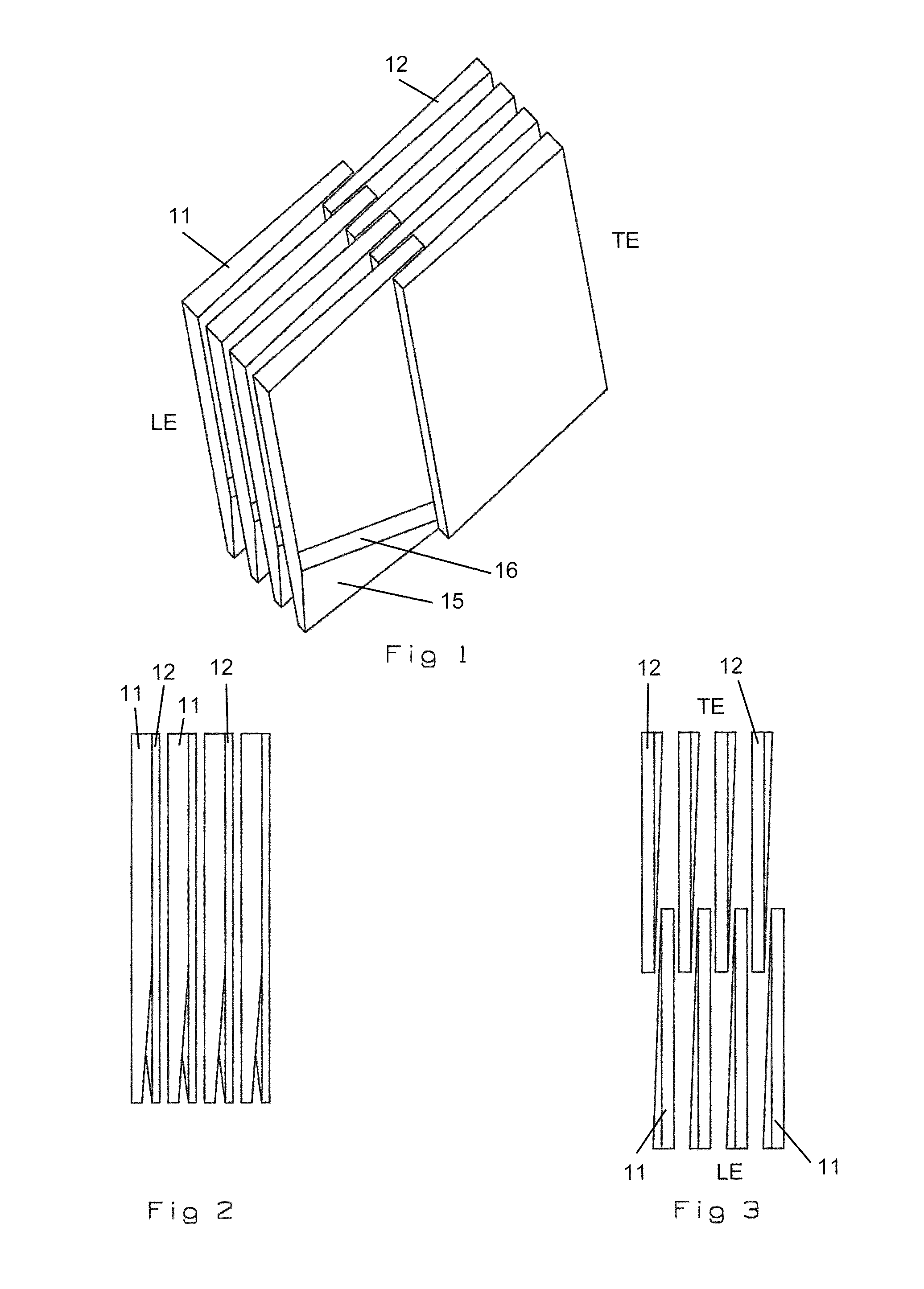
[0022]The card or leaf seal of the present invention is shown in FIGS. 1-3 where in FIG. 1 is shown a number of cards are stacked together to form the card seal. The card seal is made up of two alternating sections of cards that include an upstream or leading edge card 11 and a downstream or trailing edge card 12 when measured in the direction of the high pressure to the low pressure of the fluid in which the card seal forms a seal.

[0023]One feature of the invention is that the cards do not have a constant thickness from front to back. The card thickness is greatest on the leading edge and trailing edge, while the inner edge where the interweaving occurs is the thinnest section. FIG. 3 shows this feature best. Here, the leading edge cards 11 are thicker on the bottom of this figure that in the interweaved section, and the trailing edge cards are thicker on the top of this figure with the thinner section being at the bottom of the card in the interweaved section. The foot print of ea...


PUM


Abstract

A card seal with an annular arrangement of cards that form the card seal, where the cards are interweaved and staggered to increase a sealing capability of the cards. The card seal is formed from leading edge cards staggered with trailing edge cards, and the cards have a thicker outer end and a thinner inner end where the interweaving occurs. Because of the varying thickness of the staggered cards, each card has a taper on the lower outer end that decreases from a high to a low on the inner side in order that a foot print for the card is constant across the bottom surface that floats on the rotating part.

Description

GOVERNMENT LICENSE RIGHTS[0001]None.CROSS-REFERENCE TO RELATED APPLICATIONS[0002]None.BACKGROUND OF THE INVENTION[0003]1. Field of the Invention[0004]The present invention relates generally to a dynamic seal, and more specifically to card seal for use in turbo machines such as gas turbines, steam turbines, compressors, pumps, etc.[0005]2. Description of the Related Art[0006]including information disclosed under 37 CFR 1.97 and 1.98[0007]A gas turbine engine includes a compressor and a turbine each having multiple rows of rotor blades interspaced between stator or guide vanes. In-between each row or stage, a large pressure differential is formed. In the compressor, the pressure increases in the flow direction while in the turbine the pressure decreases. The pressure differential between adjacent stages in the compressor is smaller than in the turbine because of the greater number of stages used in the compressor.[0008]A dynamic seal is used between the rotor and the stator of the tur...

Claims


Application Information

Patent Timeline
IPC IPC(8): F01D11/02F04D29/10
CPCF04D29/102F04D29/164
Inventor DILLON, DANIEL R
Owner FLORIDA TURBINE TECH
Why Eureka
Try Eureka