
Apparatus and method for controlling thickness of a flowing ribbon of molten glass

a technology of molten glass and flow, which is applied in the direction of glass rolling apparatus, glass tempering apparatus, manufacturing tools, etc., can solve the problems of inaccurate metering, uneven thickness of the ribbon, and variation of the thickness of the final sheet, so as to prevent gas flow

Active Publication Date: 2013-03-19
CORNING INC
View PDF12 Cites 8 Cited by
  • Summary
  • Abstract
  • Description
  • Claims
  • Application Information

AI Technical Summary

Benefits of technology

The invention is a fixture that is designed to fit tightly with a pivot member, preventing gas from flowing between them. This makes it easier to control the movement of the pivot member and reduces the risk of leaks.

Problems solved by technology

Obtaining thickness uniformity of the ribbon has been a problem in both updraw and downdraw processes where the thickness characteristics of the final sheet are determined during the attenuation process by both the uniformity of initial thickness and by the uniformity of the glass viscosity.
That is, a given thickness variation in the final sheet may be the result of inaccurate metering, imperfections in the glass-contacting sides of the forming member, or by imbalances in the temperature environment of the glass that cause imperfections in the viscosity profile of the glass flowing toward the draw line.
Thickness variation in sheet glass is a problem that has been considered by the industry to be inherent in sheet drawing processes, and may manifest itself in several general types of defects, such as wedge, long period wave variations, and short period wave variations.
The longitudinal waves or thickness variations, in turn, cause distortion that is highly objectionable from an optical standpoint, particularly when objects are viewed through the glass at a sharp angle to the waves.
Unfortunately, thickness defects in the glass ribbon may not be positionally stable over long periods of time, nor may the lateral position of the ribbon itself be constant.
Thus, the pre-positioned and immovable cooling tubes may at a first instance be properly positioned, but at a second time be ill-positioned to effectively control thickness due to movement of the defect or ribbon.

Method used


Image

  • Apparatus and method for controlling thickness of a flowing ribbon of molten glass
  • Apparatus and method for controlling thickness of a flowing ribbon of molten glass
  • Apparatus and method for controlling thickness of a flowing ribbon of molten glass

Examples


Embodiment Construction

[0040]In the following detailed description, for purposes of explanation and not limitation, example embodiments disclosing specific details are set forth to provide a thorough understanding of the present invention. However, it will be apparent to one having ordinary skill in the art, having had the benefit of the present disclosure, that the present invention may be practiced in other embodiments that depart from the specific details disclosed herein. Moreover, descriptions of well-known devices, methods and materials may be omitted so as not to obscure the description of the present invention. Finally, wherever applicable, like reference numerals refer to like elements.

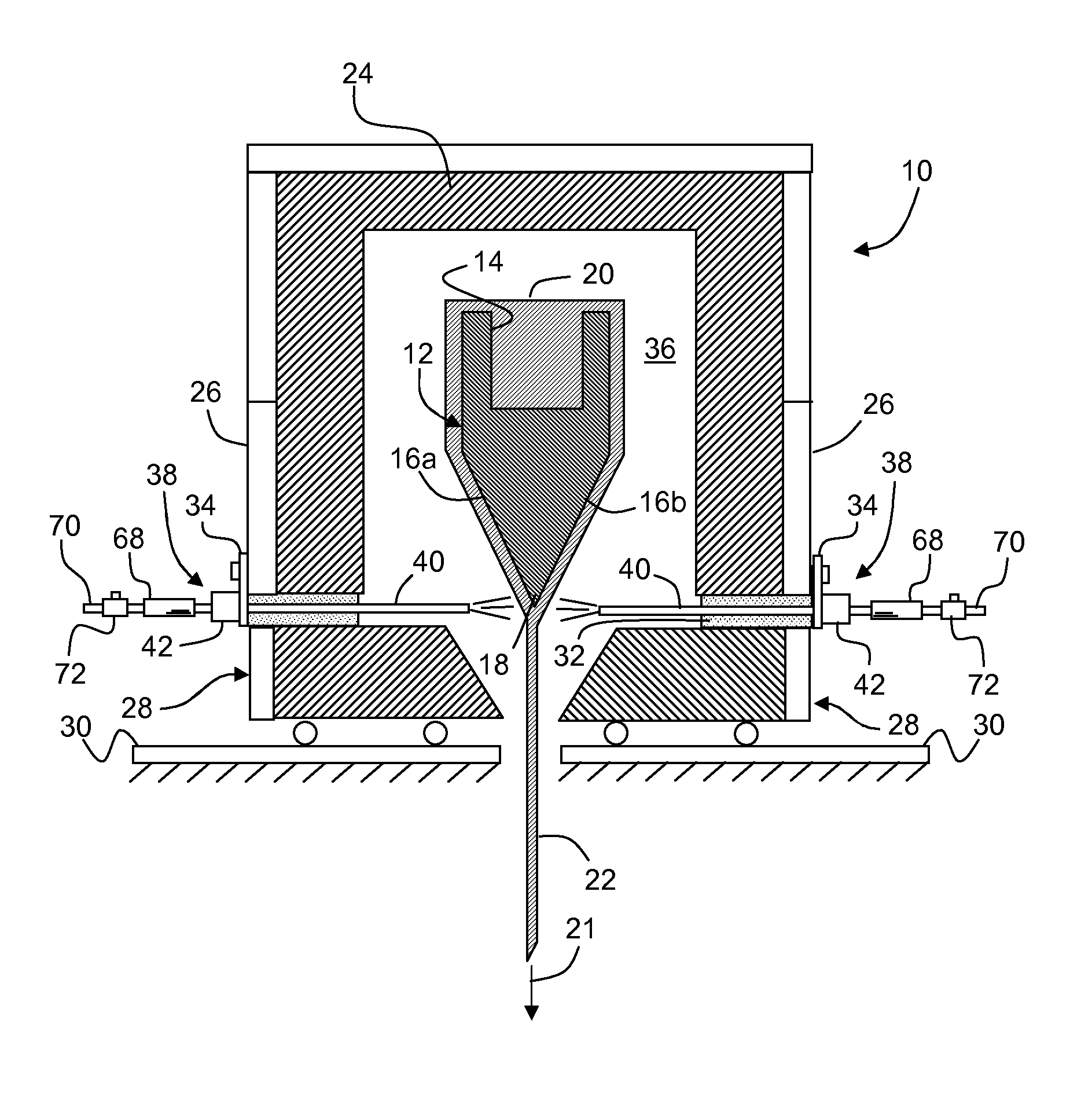
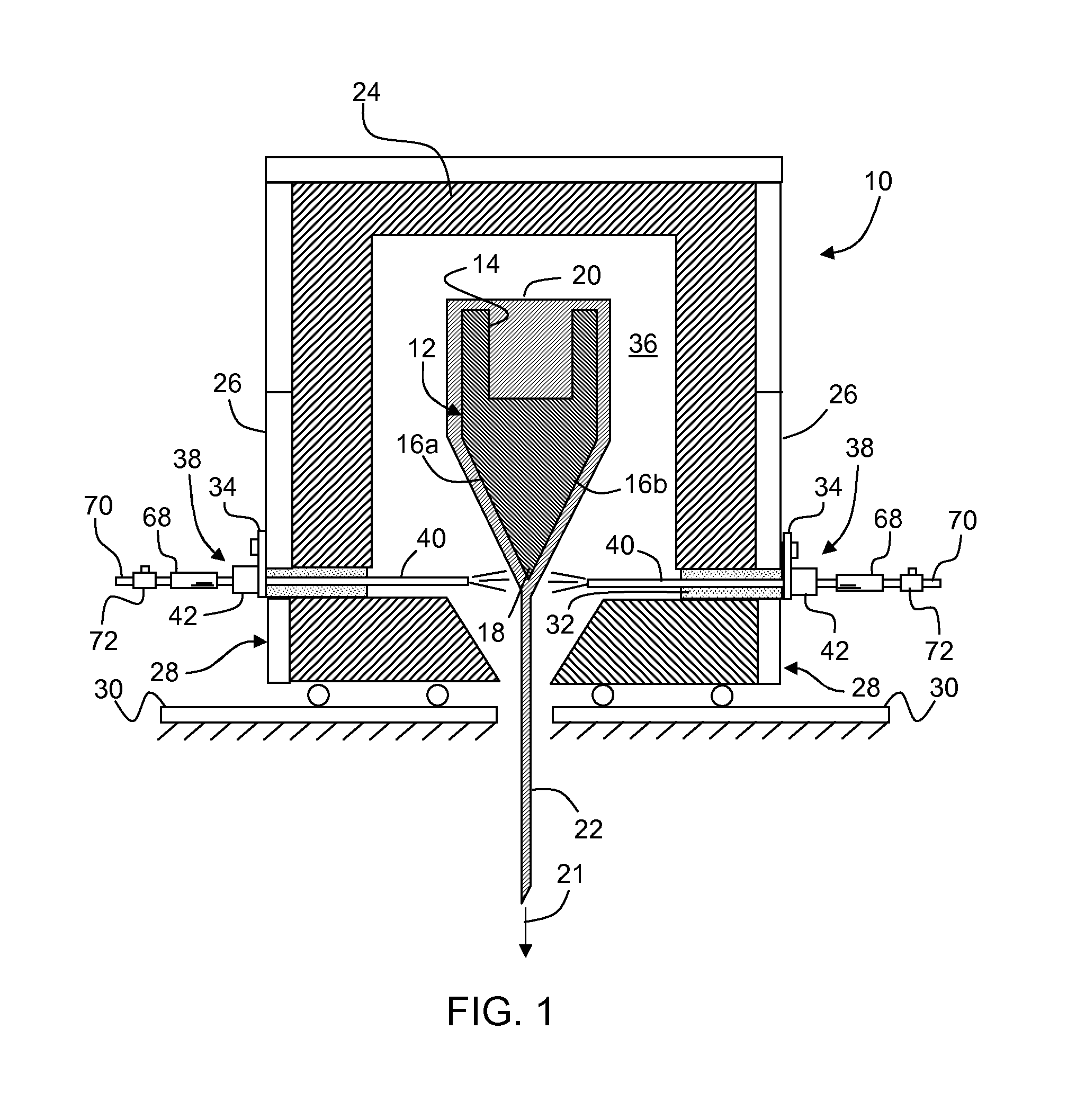
[0041]Shown in FIG. 1 is an apparatus 10 for drawing a glass ribbon according to an exemplary fusion downdraw process. Apparatus 10 comprises forming body 12 having an upper channel or trough 14 disposed therein. Forming body 12 includes converging forming surfaces 16a, 16b that converge at a lower edge or draw lin...


PUM

PropertyMeasurementUnit
thicknessaaaaaaaaaa
temperatureaaaaaaaaaa

Abstract

In the formation of sheet material from molten glass, a cooling tube is positioned in the forming area for directing a flow of cooling gas on discrete portions of the molten glass proximate a draw line or root to control local thickness variations in the sheet and thereby provide a uniform glass sheet thickness across the width of the sheet. The cooling tube is disposed in a pivot member configured to rotate about at least one axis, thereby causing an end of the cooling tube to direct the cooling gas over a wide range of angular positions across a portion of the width of the molten glass flowing over and from a forming body.

Description

CLAIMING BENEFIT OF PRIOR FILED U.S. APPLICATION[0001]This application claims the benefit of priority under 35 U.S.C. §119 to U.S. Provisional Application Ser. No. 61 / 348,516, filed on May 26, 2010, the content of which is relied upon and incorporated herein by reference in its entirety.FIELD[0002]This invention relates to a method and apparatus for controlling the thickness of a flow of molten glass, and more particularly to controlling the thickness of a continuous flow of molten glass in a downdraw glass sheet forming process.BACKGROUND[0003]When molten glass is drawn into sheet form, the glass is stretched or attenuated from an initial delivered thickness to a final sheet thickness. In the overflow downdraw process, where molten glass flows downwardly along opposed converging sides of a forming member and is withdrawn as a single ribbon of glass from the root or bottom edge thereof, the initial thickness of the glass ribbon is measured close to the bottom edge of the forming mem...

Claims


Application Information

Patent Timeline
Patent Type & Authority Patents(United States)
IPC IPC(8): C03B17/06
CPCC03B17/064C03B17/067C03B17/06C03B18/04
Inventor DELIA, ROBERTGAYLO, KEITH R.GOLYATIN, VLADISLAV Y.KOCATULUM, BULENTLALOMIA, BARRY P.WHEDON, WILLIAM A.
Owner CORNING INC
Learn More