Vertical glider robot

a vertical glider and robot technology, applied in underwater equipment, special-purpose vessels, vessel construction, etc., can solve the problems of inability to operate indefinitely, rovs are characterized by relatively limited range, and gliders cannot carry payloads other than their own weight, so as to achieve less energy

Active Publication Date: 2013-03-19
SCHLUMBERGER TECH CORP +1
View PDF15 Cites 5 Cited by
  • Summary
  • Abstract
  • Description
  • Claims
  • Application Information

AI Technical Summary

Problems solved by technology

However, at greater depths, and also when conditions are dangerous at shallow depths, the tasks are generally performed by robotic devices.
Generally, ROVs are characterized by relatively limited range because of the physical connection to the surface ship.
AUVs are not range-limited by a physical connection to the surface, but cannot operate indefinitely because they tend to exhaust their storage batteries quickly, necessitating frequent trips to the surface for recharging.
Gliders are unable to carry payloads other than their own weight.
The system is not configured to support autonomous operations.
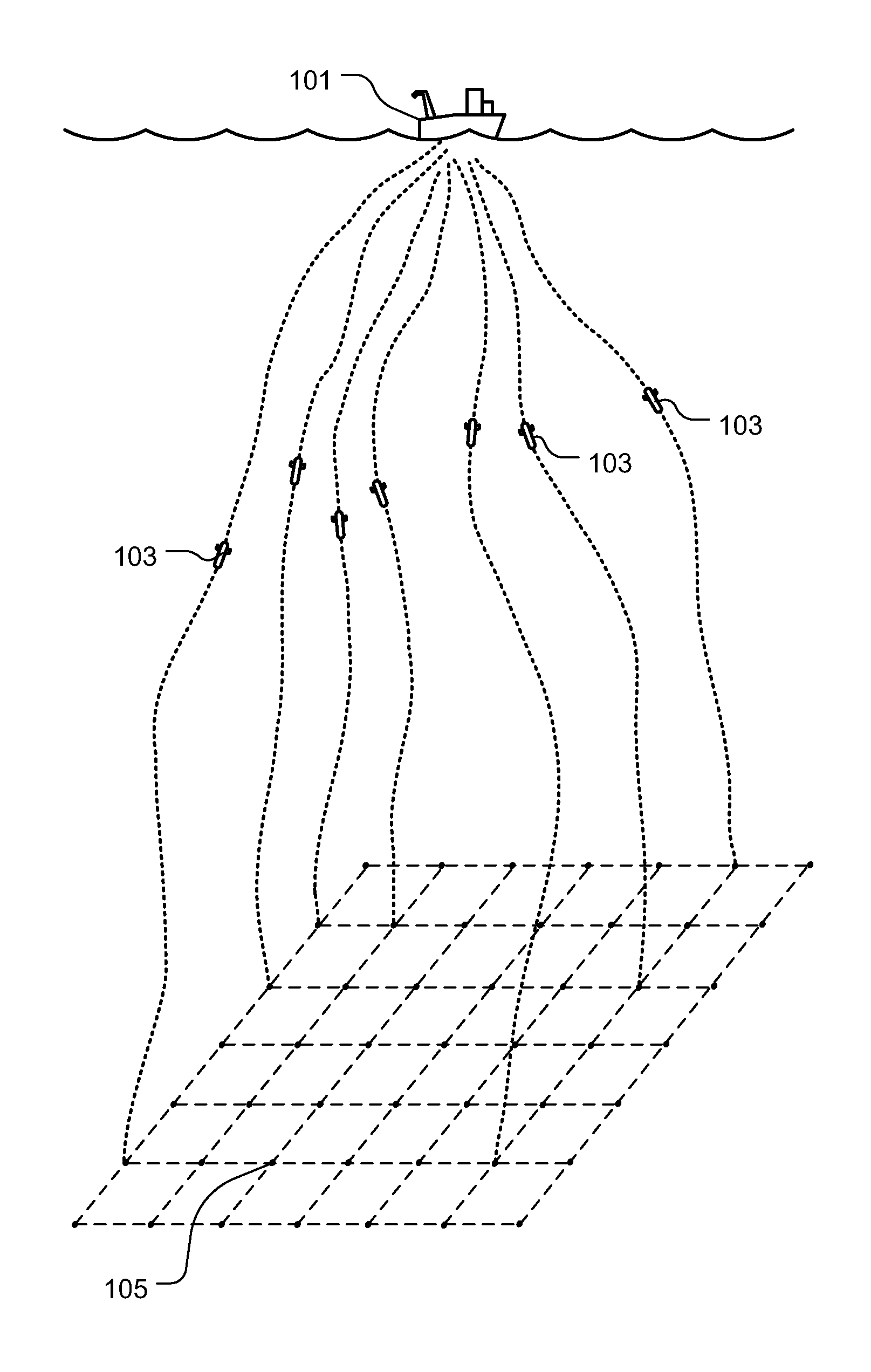
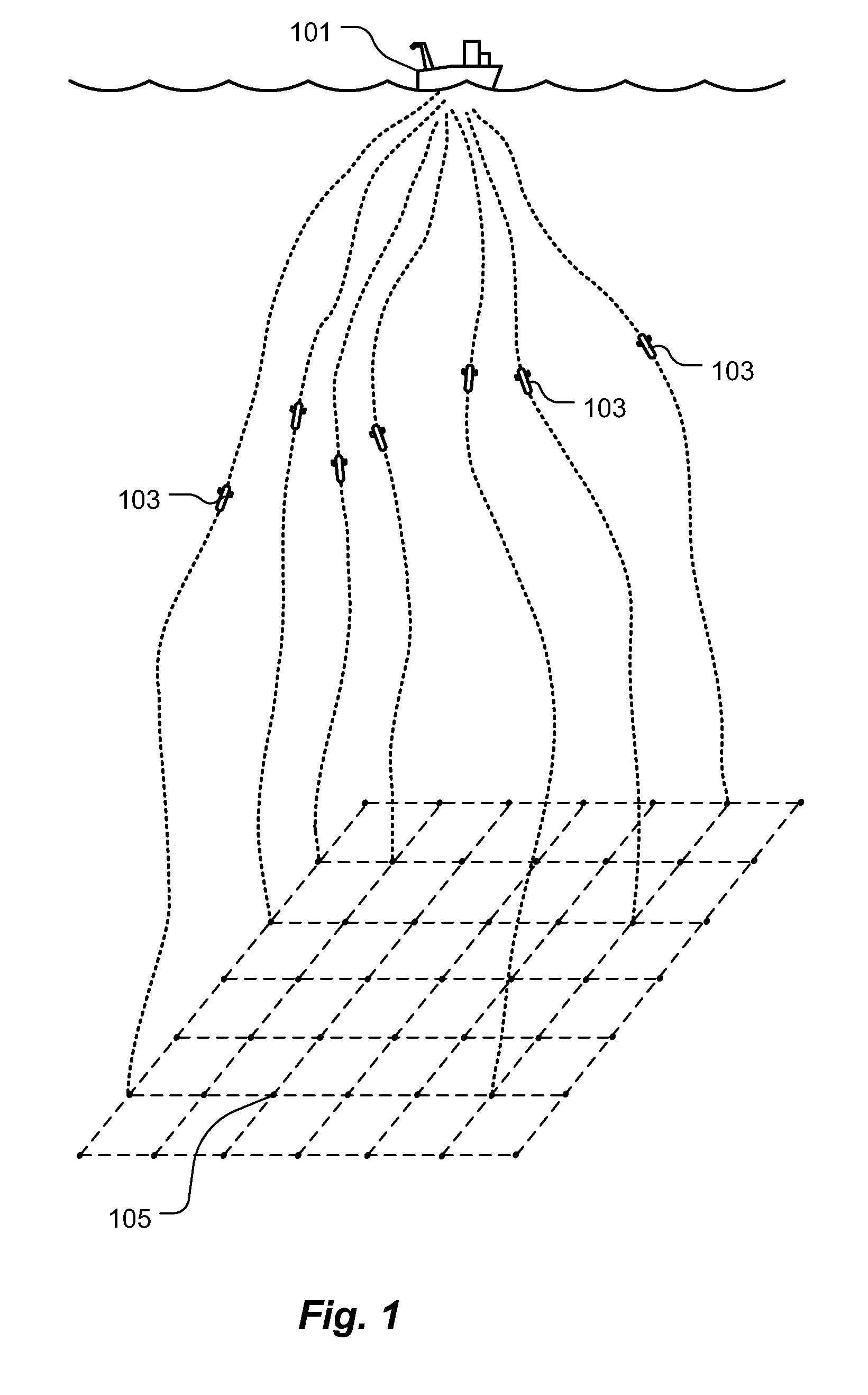
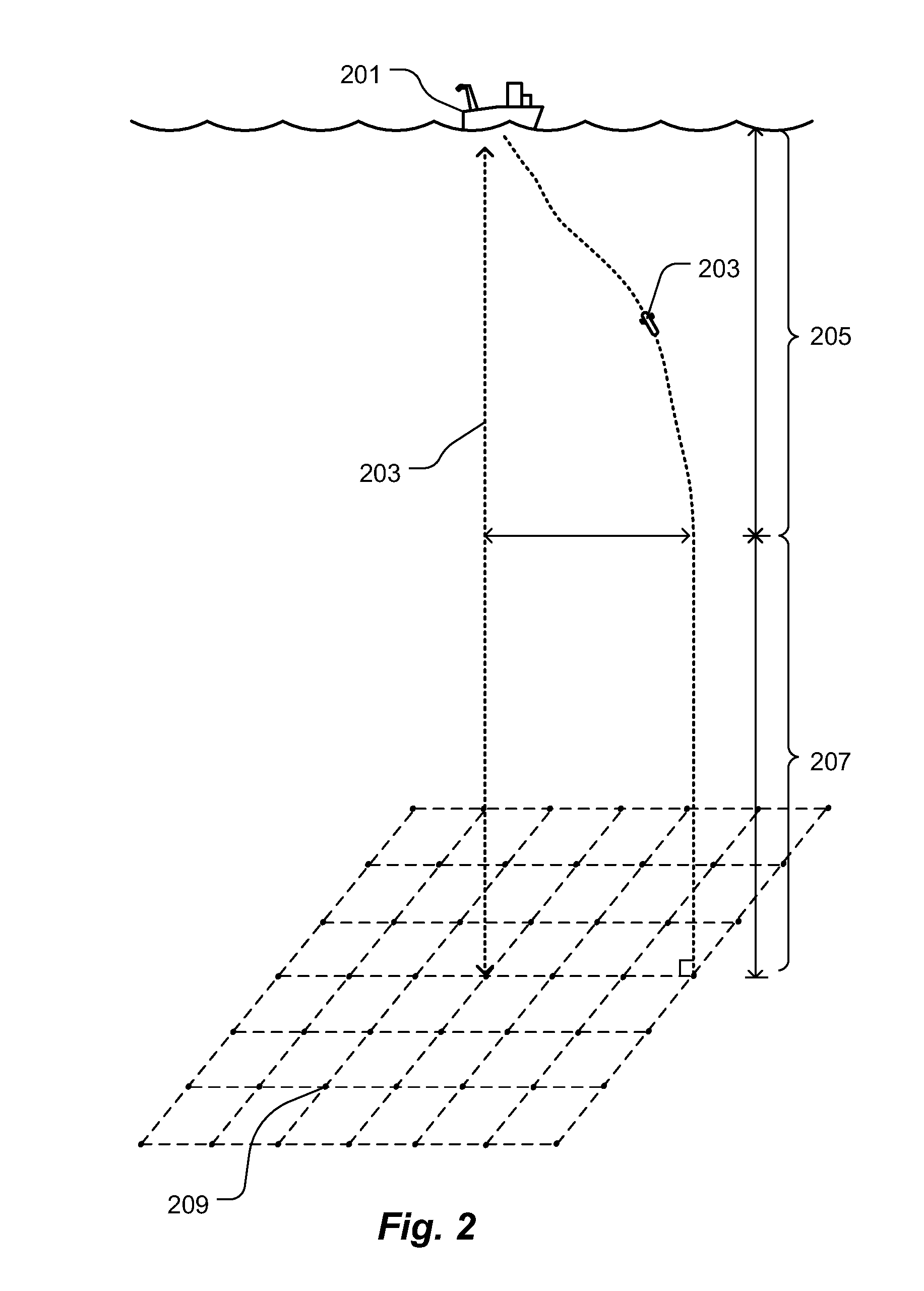
The apparatus can be substantially negatively buoyant such that the apparatus falls through the body of water towards the floor of the body of water.

Method used


Image

  • Vertical glider robot
  • Vertical glider robot
  • Vertical glider robot

Examples


Embodiment Construction

[0021]The following description provides exemplary embodiments only, and is not intended to limit the scope, applicability, or configuration of the disclosure. Rather, the following description of the exemplary embodiments will provide those skilled in the art with an enabling description for implementing one or more exemplary embodiments. It being understood that various changes may be made in the function and arrangement of elements without departing from the spirit and scope of the invention as set forth in the appended claims.

[0022]Specific details are given in the following description to provide a thorough understanding of the embodiments. However, it will be understood by one of ordinary skill in the art that the embodiments may be practiced without these specific details. For example, systems, processes, and other elements in the invention may be shown as components in block diagram form in order not to obscure the embodiments in unnecessary detail. In other instances, well-...


PUM


Abstract

A subsea vertical glider robot which supports deployment in subsea oilfield activities is disclosed. This vertical glider robot can also be used in oceanographic research exploration. One application of this vertical glider robot is the autonomous delivery of equipment and sensor systems to a precise predetermined location on the sea floor. The vertical glider robot is deployed from a surface ship or any other suitable sea surface platform and allowed to free fall to the bottom of the ocean. The traversal through the body of water is performed primarily by converting initial potential energy of the apparatus into kinetic energy, it does not use propellers. The traversing of the seafloor is controlled with a steering module that refines orientation while processing information about the vertical glider robot's current position and the target where it has to land.

Description

CROSS-REFERENCE TO RELATED APPLICATION[0001]This patent application claims the benefit of U.S. Ser. No. 61 / 289,722, filed Dec. 23, 2009, which is incorporated by reference herein.FIELD OF THE INVENTION[0002]The present invention relates to the field of oil exploration operations in a subsea environment. More specifically, the invention relates to an apparatus and method for supporting deployment of equipment or sensors on the sea floor of areas where oilfield exploration or oceanographic activities occur.BACKGROUND OF THE INVENTION[0003]In order to recover natural resources from underwater subterranean formations it is often necessary to perform exploration, monitoring, maintenance and construction operations on or beneath the sea floor. In relatively shallow depths these tasks can be performed by divers. However, at greater depths, and also when conditions are dangerous at shallow depths, the tasks are generally performed by robotic devices. Various types of robotic devices are kno...

Claims


Application Information

Patent Timeline
Patent Type & Authority Patents(United States)
IPC IPC(8): B63G8/00
CPCG01V3/12B63B51/00
Inventor GUERRERO, JULIOHOVER, FRANZAMBLER, CHARLESREED, BROOKSHUMMEL, ROBERT
Owner SCHLUMBERGER TECH CORP
Why Eureka
Try Eureka