Receptacle assembly

a technology of receptacles and assemblies, applied in the direction of coupling device connections, coupling protective earth/shielding arrangements, electrical apparatus, etc., can solve the problems of insufficient electrical connectors, signal loss and/or signal degradation in known electrical systems, and further strain on performan

Active Publication Date: 2013-03-19
TYCO ELECTRONICS LOGISTICS AG (CH)
View PDF12 Cites 41 Cited by
  • Summary
  • Abstract
  • Description
  • Claims
  • Application Information

AI Technical Summary

Problems solved by technology

Signal loss and / or signal degradation is a problem in known electrical systems.
Moreover, as speed and performance demands increase, known electrical connectors are proving to be insufficient.
Such increase in density and / or reduction in size causes further strains on performance.
However, the shielding utilized in known systems is not without disadvantages.
For instance, electrically connecting the grounded components of the two electrical connectors at the mating interface of the electrical connectors is difficult and defines an area where signal degradation occurs due to improper shielding at the interface.

Method used


Image

  • Receptacle assembly
  • Receptacle assembly
  • Receptacle assembly

Examples


Embodiment Construction

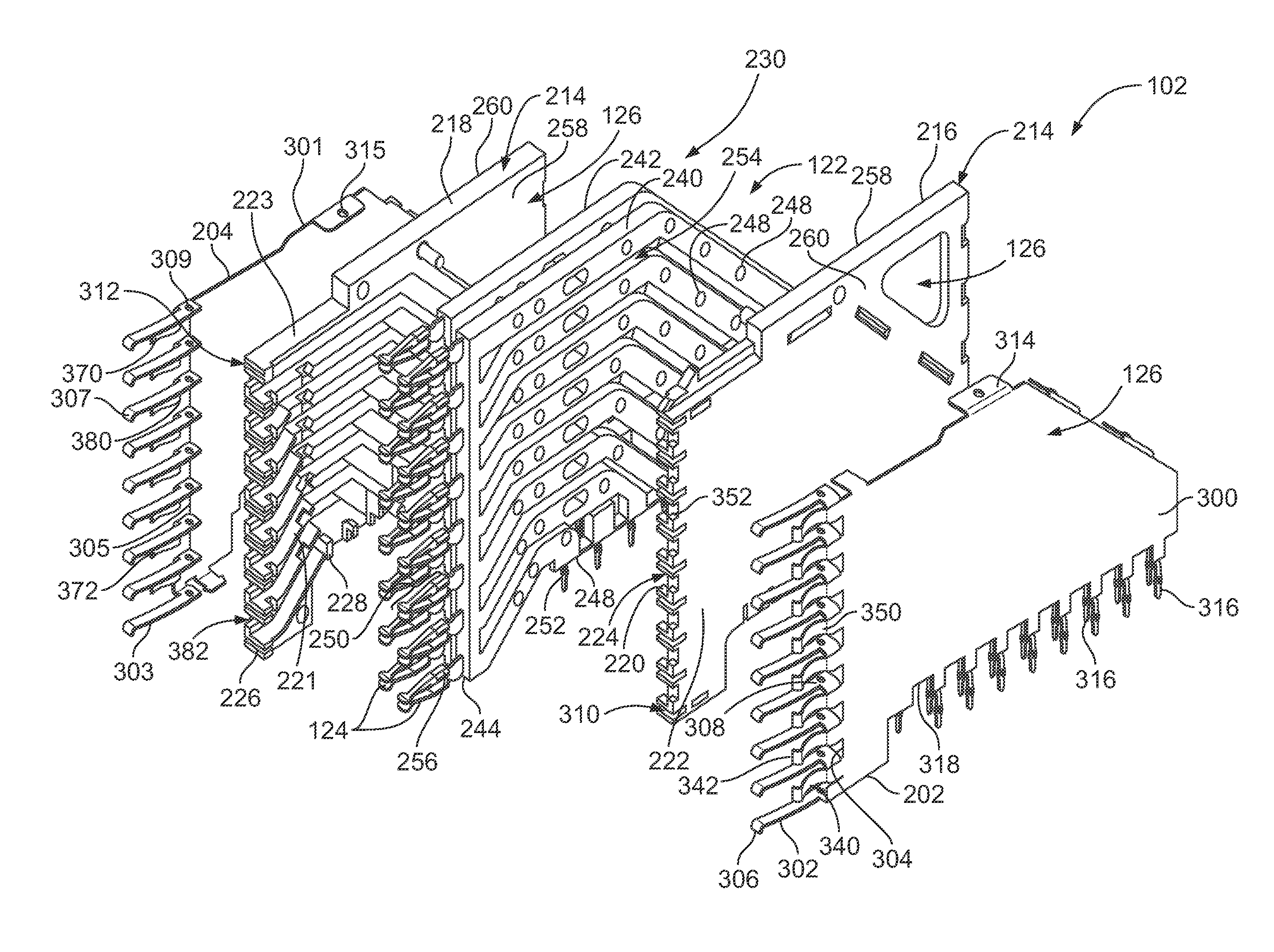
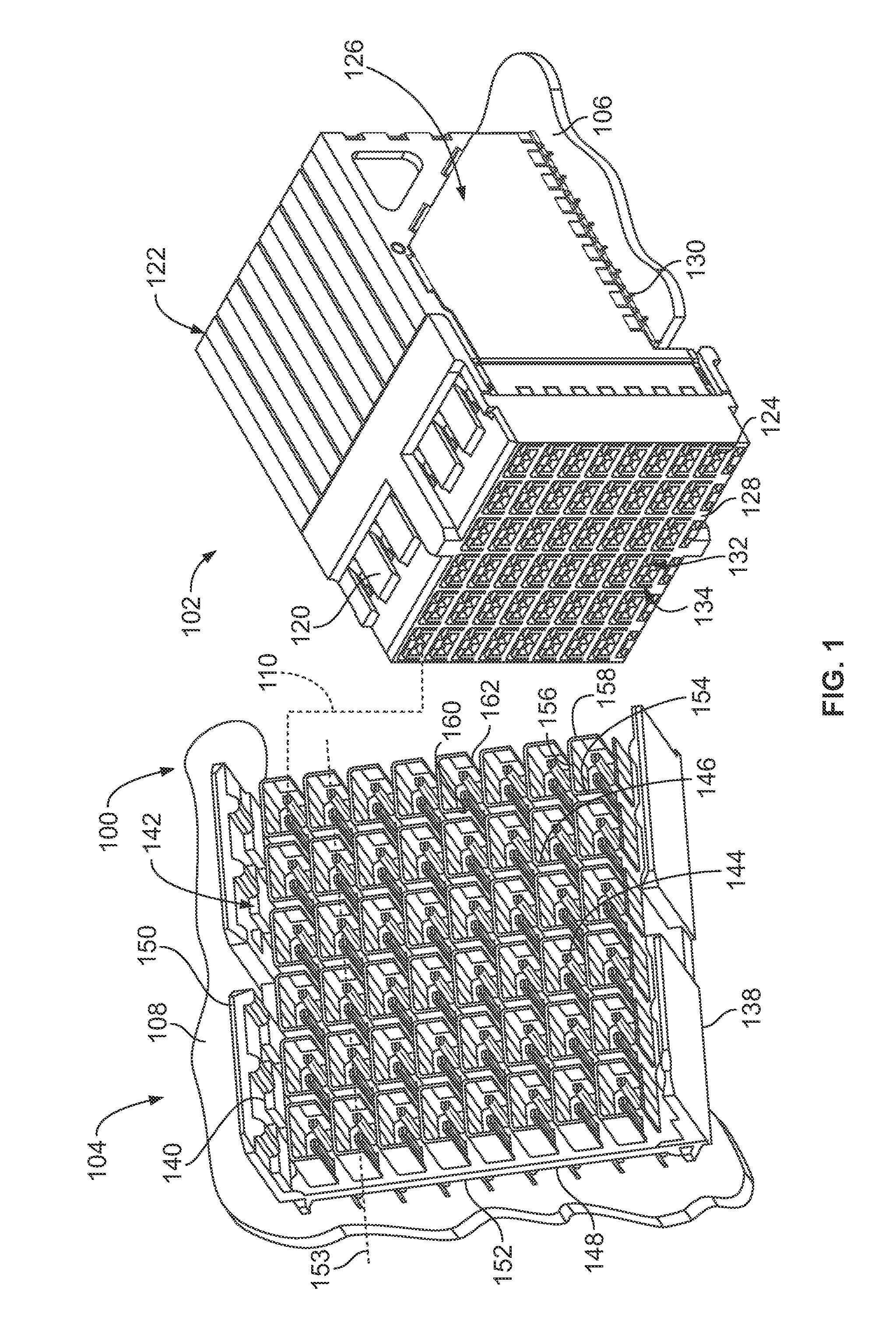
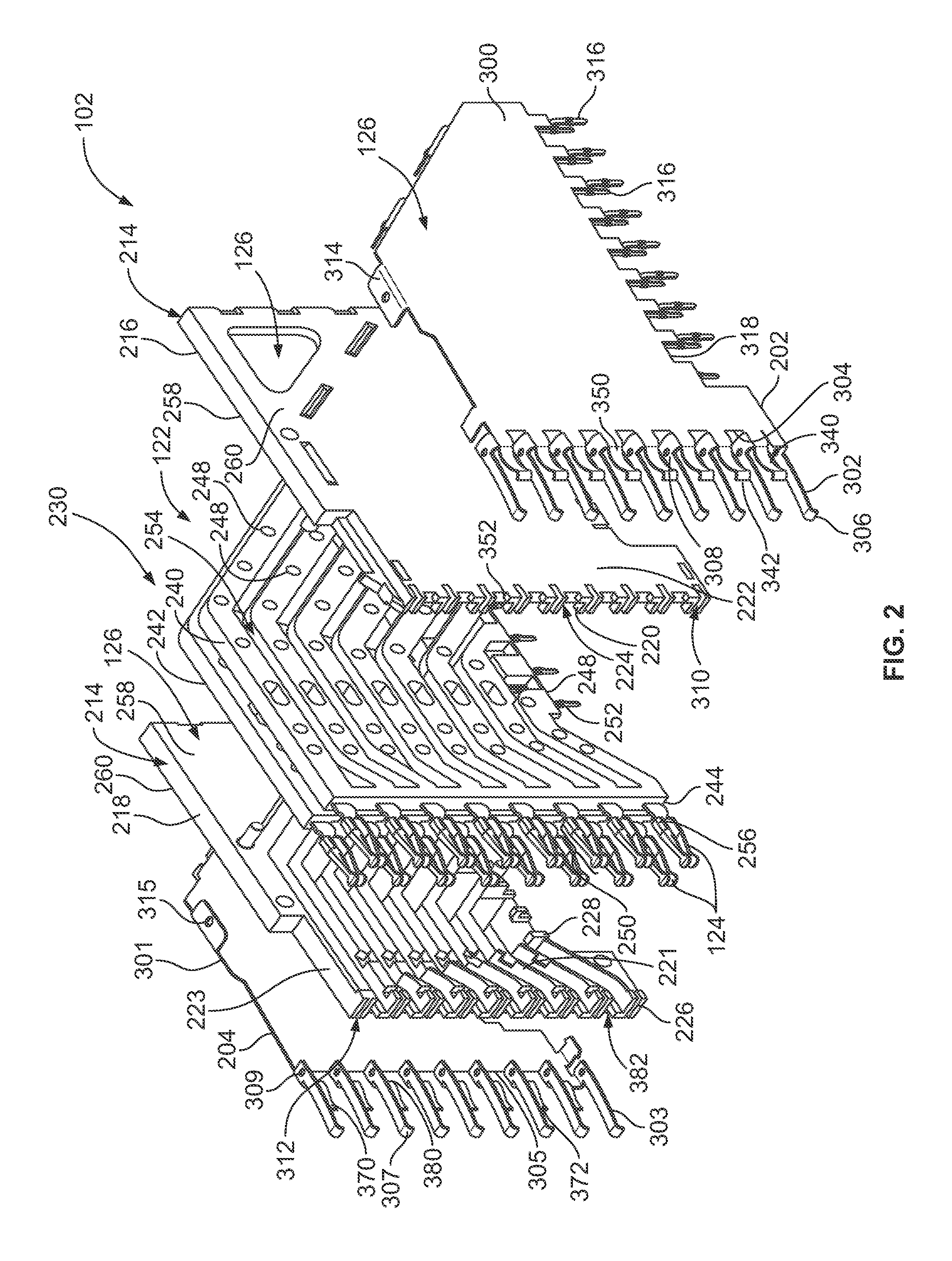
[0013]FIG. 1 is a perspective view of an exemplary embodiment of an electrical connector system 100 illustrating a receptacle assembly 102 and a header assembly 104 that may be directly mated together. The receptacle assembly 102 and / or the header assembly 104 may be referred to hereinafter individually as a “connector assembly” or collectively as “connector assemblies”. The receptacle and header assemblies 102, 104 are each electrically connected to respective circuit boards 106, 108. The receptacle and header assemblies 102, 104 are utilized to electrically connect the circuit boards 106, 108 to one another at a separable mating interface. In an exemplary embodiment, the circuit boards 106, 108 are oriented perpendicular to one another when the receptacle and header assemblies 102, 104 are mated. Alternative orientations of the circuit boards 106, 108 are possible in alternative embodiments.

[0014]A mating axis 110 extends through the receptacle and header assemblies 102, 104. The ...


PUM


Abstract

A receptacle assembly includes a front housing configured for mating with a header assembly and a contact module coupled to the front housing. The contact module includes a conductive holder having a first side wall and an opposite second side wall and a front coupled to the front housing. The conductive holder holds a frame assembly having a plurality of contacts and a dielectric frame supporting the contacts. The dielectric frame is received in the conductive holder and the contacts extend from the conductive holder for electrical termination. A ground shield is coupled to the first side wall. The ground shield is electrically connected to the conductive holder. The ground shield has grounding beams extending therefrom that extend forward of the front of the conductive holder for electrical connection to an interior surface of a corresponding header shield of the header assembly. The ground shield has grounding fingers extending therefrom forward of the front of the conductive holder for electrical connection to an interior surface of the corresponding header shield of the header assembly.

Description

BACKGROUND OF THE INVENTION[0001]The subject matter herein relates generally to connector assemblies.[0002]Some electrical systems utilize electrical connectors to interconnect two circuit boards, such as a motherboard and daughtercard. Signal loss and / or signal degradation is a problem in known electrical systems. For example, cross talk results from an electromagnetic coupling of the fields surrounding an active conductor or differential pair of conductors and an adjacent conductor or differential pair of conductors. The strength of the coupling generally depends on the separation between the conductors, thus, cross talk may be significant when the electrical connectors are placed in close proximity to each other.[0003]Moreover, as speed and performance demands increase, known electrical connectors are proving to be insufficient. Additionally, there is a desire to increase the density of electrical connectors to increase throughput of the electrical system, without an appreciable ...

Claims


Application Information

Patent Timeline
Patent Type & Authority Patents(United States)
IPC IPC(8): H01R13/648
CPCH01R13/6471H01R13/6587
Inventor WHITEMAN, JR., ROBERT NEILDAVIS, WAYNE SAMUEL
Owner TYCO ELECTRONICS LOGISTICS AG (CH)
Why Eureka
Try Eureka