Culture apparatus

a technology of culture apparatus and sterilization gas, which is applied in the direction of material analysis using wave/particle radiation, biomass after-treatment, nuclear engineering, etc., can solve the problems of incomplete sterilization of heat-resistant germs, and insufficient sterilization of culture apparatus. , to achieve the effect of efficient sterilization of the inside of the apparatus, effective generation of sterilization gas, and simplified apparatus configuration

Active Publication Date: 2013-03-19
PHC HLDG CORP
View PDF18 Cites 3 Cited by
  • Summary
  • Abstract
  • Description
  • Claims
  • Application Information

AI Technical Summary

Benefits of technology

[0008]The present invention has made to overcome such a problem and it is an object of the invention to provide a culture apparatus which is capable of shortening a sterilization time and sterilizing the culture apparatus including a gas concentration measuring sensor, pipes connected to a gas concentration measuring device and every corner of a cultivating chamber.

Problems solved by technology

However, this technique could not thoroughly sterilize the culture apparatus including the gas concentration measuring sensor, the pipes connected to the gas concentration measuring device and every corner of the cultivating chamber.
In addition, heat-resistant germs are incompletely sterilize even at the high temperature of more than 90° C., and further, about 8 hours are required to restart the cultivation through a cooling process from the increase of temperature of the cultivating chamber for sterilization by heating.
This may lead to a problem of too much time during which the culture apparatus can not be used for cultivation.

Method used


Image

  • Culture apparatus
  • Culture apparatus
  • Culture apparatus

Examples


embodiment 1

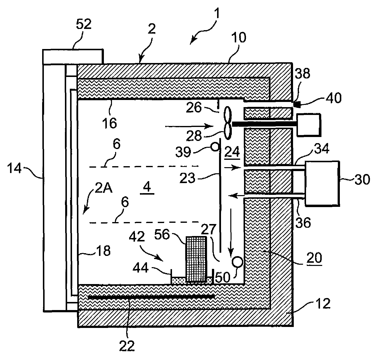
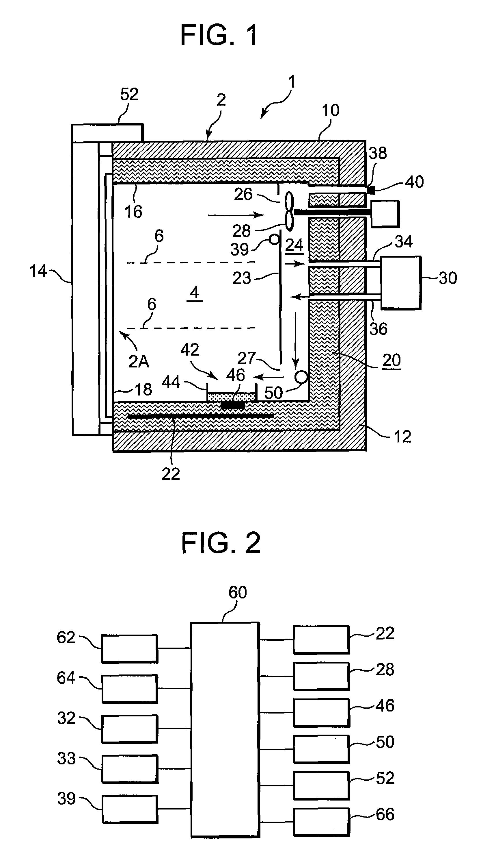
[0028]Hereinafter, embodiments of the present invention will be described with reference to the drawings. FIG. 1 is an end side view showing a structure of a culture apparatus 1 according to an embodiment of the present invention, and FIG. 2 is a block diagram of a control circuit for controlling the culture apparatus 1 of the present invention.

[0029]In this embodiment, as shown in FIG. 1, the culture apparatus 1 includes an insulating box body 2 comprising an outer metal box 10 having an opening 2A at one side thereof and an inner stainless box 16. In addition, the opening 2A of the inner box 16 is provided with a transparent inner door 18 whose right side is supported to the insulating box body 2 by a hinge in a free-opening / closing manner. The inner door 18 blocks the opening 2A air-tightly by means of a gasket (not shown) provided in the opening 2A of the insulating box body 2.

[0030]A cultivating chamber 4 is formed in a space (inner box 16) surrounded by an inner door 18 blocki...

embodiment 2

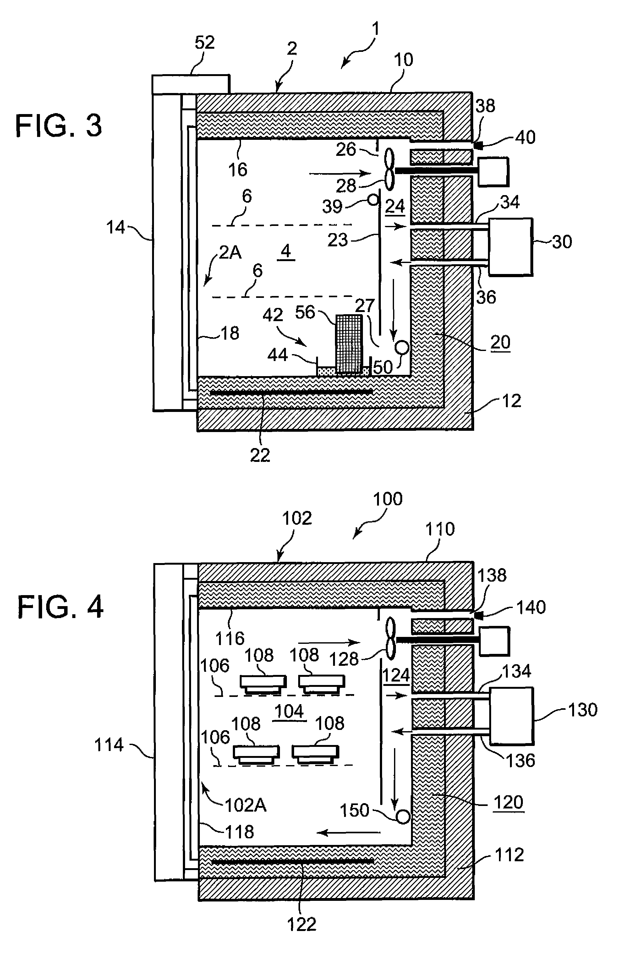
[0052]Next, FIG. 3 shows a culture apparatus 1 according to another embodiment of the present invention. The culture apparatus 1 of this embodiment has substantially the same configuration as the above-described embodiment. Hereinafter, only portions different from the above-described embodiment will be described. In the figure, the same elements as the above-described embodiment are denoted by the same reference numerals, and explanation of which will be omitted. As shown in FIG. 3, in the culture apparatus 1, the ultrasonic vibrator 46 of the sterilizing gas generator 42 in Embodiment 1 is replaced with an absorbing member 56. When the absorbing member 56 is dipped into oxygenated water, the oxygenated water is evaporated.

[0053]That is, the sterilizing gas generator 42 is provided with the absorbing member 56 erecting in the vessel 44 having flat bottom. A frame (not shown) made of stainless steel or synthetic resin is provided around the absorbing member 56. A given wide nonwoven...


PUM

PropertyMeasurementUnit
temperatureaaaaaaaaaa
timeaaaaaaaaaa
concentrationaaaaaaaaaa

Abstract

A culture apparatus which is capable of shortening sterilization time includes a gas concentration measuring sensor, pipes connected to a gas concentration measuring device and every corner of a cultivating chamber, and a sterilizing gas generator that supplies sterilizing gas into a cultivating chamber and atomizes a sterilizer solution (oxygenated water) by means of an ultrasonic vibrator. The culture apparatus further includes an ultraviolet lamp that irradiates gas in the cultivating chamber, a freely opening / closing door, a door-locking device, and a controller for controlling the locking device to prevent the door from being opened from start of the sterilization process to end of the decomposition process.

Description

BACKGROUND OF THE INVENTION[0001]This invention relates to a culture apparatus for cultivating (or incubating) cultures such as cells, microbes and the like in a cultivating chamber.[0002]A culture apparatus, which has been conventionally called an incubator, cultivates cultures (samples) such as cells, microbes and the like as culture targets in an aseptic cultivating chamber while keeping temperature of the cultivating chamber and gas concentration of carbon dioxide (CO2), Oxygen (O2) or the like constant. As shown in FIG. 4, a culture apparatus 100 includes an insulating box body 102 comprising an outer metal box 110 having an opening 102A at one side thereof and an inner stainless box 116 provided inside the outer box 110. In addition, a cultivating chamber 104 is formed in a space (inner box 116) surrounded by a door (inner door 118) blocking the opening 102A in a free-opening / closing manner. The cultivating chamber 104 is vertically partitioned by a plurality of shelves 106 on...

Claims


Application Information

Patent Timeline
Patent Type & Authority Patents(United States)
IPC IPC(8): A61L2/00C12M1/34A61L9/00G01N21/00A24F25/00
CPCA61L2/186C12M41/48C12M41/14C12M37/00C12M1/00C12M1/04C12M1/12
Inventor BUSUJIMA, HIROKI
Owner PHC HLDG CORP
Why Eureka
Try Eureka