Focused plenoptic camera employing microlenses with different focal lengths
a technology of microlenses and focused plenoptic cameras, which is applied in the field of focused plenoptic cameras employing microlenses with different focal lengths, can solve the problems of inability to capture a perfectly in-focus 2d image of the 3d world, conventional cameras fail to capture a large amount of optical information, and the image contains no information about the direction of light, etc., to achieve the effect of reducing the number of focal lengths, reducing the number of focal length
- Summary
- Abstract
- Description
- Claims
- Application Information
AI Technical Summary
Benefits of technology
Problems solved by technology
Method used
Image
Examples
example results
[0122]Some embodiments of a focused plenoptic camera as described herein may be implemented in film cameras. Embodiments may, for example, be implemented in large-format film cameras. An example large-format film camera embodiment is illustrated in FIG. 8. One example embodiment may, for example, be implemented in large-format film camera using a 135 mm objective lens and 4×5 format film. A focused plenoptic camera based on a large-format film camera rather than on a digital camera may be used for experimental purposes in order to avoid resolution constraint of digital sensors. However, film camera embodiments of the focused plenoptic camera design are practical and may have practical applications. In conjunction with current high-resolution scanners used to digitize captured images from negatives or prints, large-format film camera embodiments are capable of 1 gigapixel, or even higher, resolution for the flat (2D) representation of the 4D radiance (the raw flat).
[0123]A component ...
example embodiment
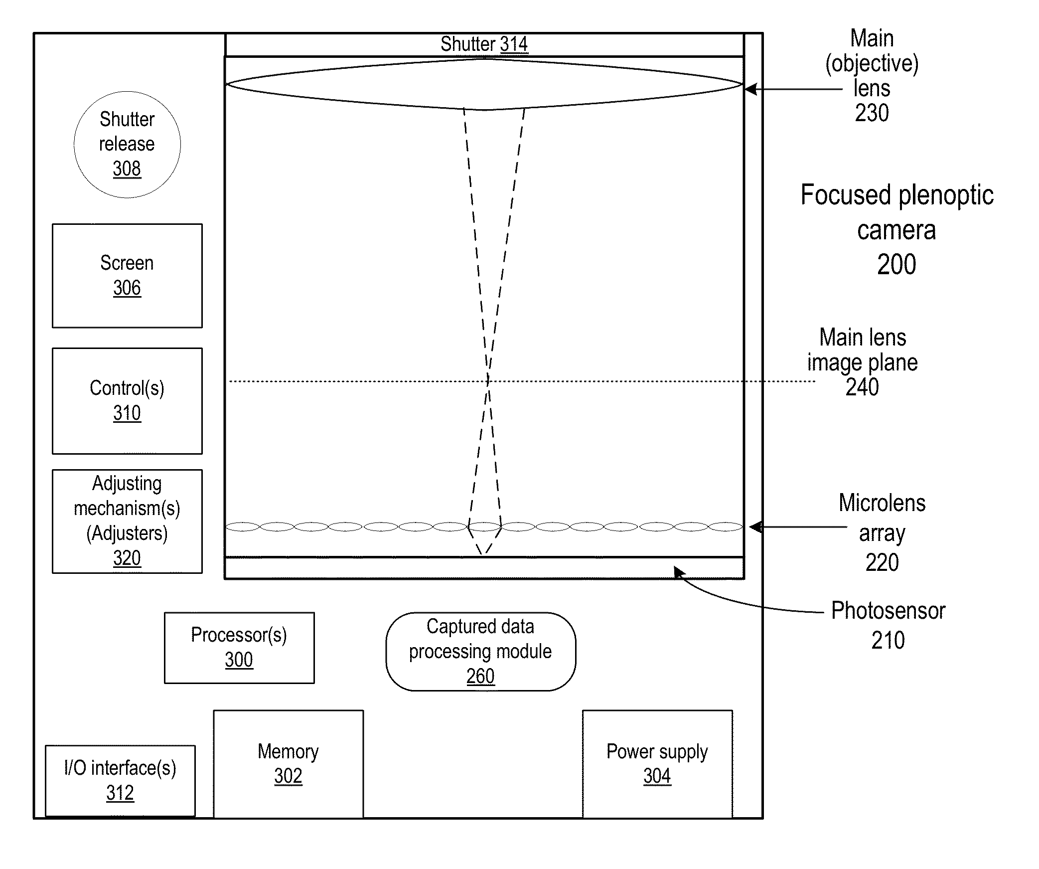
[0205]FIG. 38 is a block diagram illustrating an example embodiment of a focused plenoptic camera that includes an array of optical elements in which different ones of the optical elements provide different focal lengths. This embodiment employs microlens stacks, each including two microlenses, formed by stacking two microlens arrays 2420 on top of each other, similar to the examples shown in FIGS. 33, 34B, and 37. Note that, in FIG. 38, as in the other Figures, the number of elements, the distances between elements, the sizes of the elements, and the relative sizes of the elements when compared to each other are illustrative and are not intended to be limiting. Furthermore, values for various dimensions, optical numbers (such as F-numbers), distances, and so on are given by way of example, and are not intended to be limiting.
[0206]In this example embodiment, the first microlens array 2420A is placed directly on the photosensor cover glass 2412 with the mircolenses facing the glass ...
example modes
and Applications
[0231]FIGS. 48A through 48D illustrate several example modes or configurations of a focused plenoptic camera employing microlenses with different focal lengths, according to various embodiments. These various modes may be directed to different applications. The various modes may be achieved by various configurations of the optical element arrays that provide different focal lengths as described above. Embodiments of a focused plenoptic camera may be configured to operate in one, two, or more of these modes. In addition, some embodiments of a focused plenoptic camera may be configured so that the camera may be modified to operate in two or more of the modes, for example by swapping out an optical element array for a different optical element array, or by swapping out a component (e.g., one wafer) of an optical element array for another component.
[0232]The shaded ellipses in FIGS. 48A through 48D represent the virtual 3D image of a real scene in front of the camera tha...
PUM
 Abstract
Description
Claims
Application Information
 - R&D
- Intellectual Property
- Life Sciences
- Materials
- Tech Scout
- Unparalleled Data Quality
- Higher Quality Content
- 60% Fewer Hallucinations
Browse by: Latest US Patents, China's latest patents, Technical Efficacy Thesaurus, Application Domain, Technology Topic, Popular Technical Reports.
© 2025 PatSnap. All rights reserved.Legal|Privacy policy|Modern Slavery Act Transparency Statement|Sitemap|About US| Contact US: help@patsnap.com


