Mounting device for securing plate-shaped elements

a technology for mounting devices and plate-shaped elements, which is applied in the direction of heat collector mounting/support, building scaffolds, domestic objects, etc., can solve the problems of time-consuming and expensive difficult mounting of solar panels, etc., and achieves simple and rapid mounting of mounting devices, simple manufacturing of mounting devices, and the effect of reducing the cost of mounting plate-shaped elements

Inactive Publication Date: 2013-03-26
HILTI AG
View PDF16 Cites 13 Cited by
  • Summary
  • Abstract
  • Description
  • Claims
  • Application Information

AI Technical Summary

Benefits of technology

[0009]The at least one resilient element presses the first holding member and the second holding member away from each other, which insures a minimal distance therebetween in the release condition of the mounting device. Thus, the receiving space between the two holding members has an adequate height for a correspondingly formed plate-shaped element, and the plate-shaped element, e.g., a solar panel can be conveniently inserted in the receiving space and secured on the mounting rail with the mounting device. Separate parts or elements of the mounting device are advantageously connected with each other without a possibility of being lost.
[0011]Advantageously, there are provided, on the adjacent, to each other, sides of the two holding members which come into contact with the plate-shaped element upon locking of the mounting device, elastic pads. The elastic pads prevent contact of the rigid regions of the holding members with the edge region of the plate-shaped element. Thereby, damage of the plate-shaped element, which might have been caused by securing of the plate-shaped element, is prevented.
[0013]Advantageously, the mounting device has a rear gripping member with an anchoring element for the fastening member. This provides for a simple and rapid mounting of the mounting device in a receiving groove of the mounting rail. The fastening member advantageously has a shaft that advantageously is provided with a threaded section at least in one region. The threaded section is engageable with a counter-thread provided in the rear gripping member as an anchoring element. The mounting device is available to the user advantageously in pre-assembled condition. The rear gripping member is advantageously connected with the shaft of the fastening member without a possibility of rotation relative thereto and further advantageously releasably. The rear gripping member and, e.g., the opposite end of the fastening member limit the maximal displacement of the two holding members toward each other.
[0014]Advantageously, the at least one resilient element is formed as an easily compressible elastomeric body that can expand to a sufficiently large predetermined mass in its expanded condition. Alternatively, the at least one resilient element can be formed of sponge rubber or neoprene, or as a spring formed of metal or plastic material, e.g., in form of a plate, spiral or helical spring.
[0015]Advantageously, at least one first guide web projects from a side of the first holding member adjacent to the second holding member and at least one second guide web projects from a side of the second holding member adjacent to the first holding member. The first and second guide webs overlap each other and extend in opposite directions toward each other. As a result, the two holding members can be displaced relative to each other. Simultaneously, both the first holding member and the second holding member are secured against rotation, e.g., about a longitudinal axis of the fastening member. This insures that the holding members are always aligned parallel to the edges of the plate-shaped element during the entire mounting process of the plate-shaped element. Thereby, the costs of mounting of plate-shaped elements are noticeably reduced because no alignment is necessary during or after locking of the mounting device.
[0016]Advantageously, the at least resilient element is provided between one of the free edges or a free end side of a guide web and the opposite holding member. This insures a simple manufacturing of the mounting device and, at the same time, makes it highly assembly-friendly.

Problems solved by technology

The drawback of the above-described mounting device consists in that during mounting of the device on a mounting rail, the first and second holding members tend to automatically adjust themselves to a minimal distance therebetween predetermined by the spacer sleeve.
This makes mounting of a solar panel more difficult because its edge should be inserted in several mounting devices.
In particular, with large surfaces of the solar panels and, e.g., when two adjacent to each other solar panels need to be secured with a single mounting device, the mounting of the solar panels is time-consuming and expensive.

Method used


Image

  • Mounting device for securing plate-shaped elements
  • Mounting device for securing plate-shaped elements
  • Mounting device for securing plate-shaped elements

Examples


Embodiment Construction

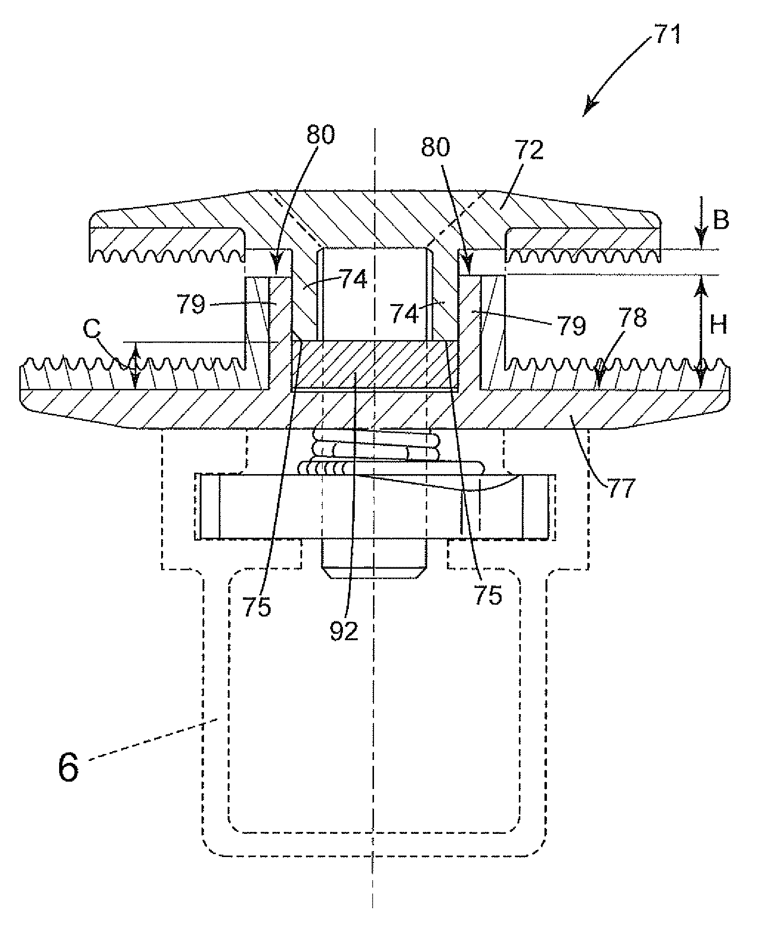
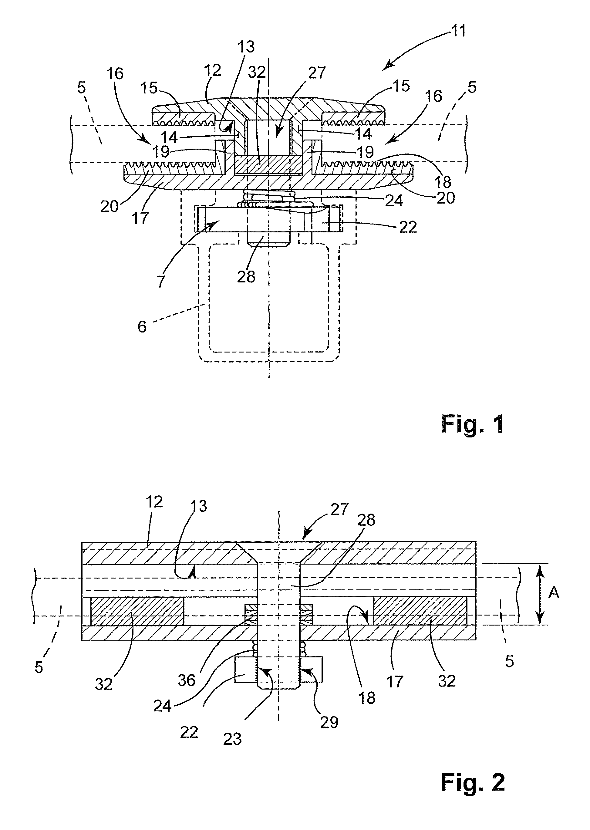
[0028]A mounting device 11 according to the present invention, which is shown in FIGS. 1-2, is formed as a central clamp for securing of plate-shaped elements 5, such as solar panels, in a receiving groove 7 of a mounting rail 6 that serves as a support element for the plate-shaped elements 5. The mounting device 11 includes a first holding member 12 that is used as a holding-down member for holding a plate-shaped element 5, a second holding member 17 that is used as a support member for the plate-shaped panel 5, a rear gripping member 22 insertable into receiving groove 7 of the mounting rail 6 and rotatable therein, and a fastening member 27 having a shaft 28. The shaft 28 of the fastening member 27 extends through the first and second holding members 12 and 17 and engages with a threaded section 29, which is formed in a region of the shaft 28, an inner thread provided in the rear gripping member 22 and forming an anchoring element of the mounting rail 6. Between the first holding...


PUM


Abstract

A mounting device for securing plate-shaped elements (5) on a mounting rail (6) includes first (12; 52; 72) and second holding members (17; 57; 77) forming, together a space (16; 42) for receiving a plate-shaped element (5), a fastening member (27; 60) extending through the first (12; 52; 72) and the second (17; 57; 77) holding member and connectable with an anchoring element (23) provided on the mounting rail (6) for securing the mounting device (11; 41; 51; 71) on the mounting rail (6), and at least one resilient element (32; 46; 62; 92) provided between the first holding member (12; 52; 72), which is displaceable relative to the second holding member, and the second holding member (17; 57; 77) for spacing the first and second holding members (12, 17; 52, 57; 72, 77) from each other.

Description

BACKGROUND OF THE INVENTION[0001]1. Field of the Invention[0002]The present invention relates to a mounting device for securing plate-shaped elements on a mounting rail and including a first holding member, a second holding member forming, together with the first holding member, a space for receiving a plate-shaped element, with the first holding member being displaceable relative to the second holding member, and a fastening member extending through the first holding member and the second holding member and connectable with an anchoring element provided on the mounting rail for securing the mounting device on the mounting rail.[0003]2. Description of the Prior Art[0004]For mounting plate-shaped elements such as solar panels of solar plants on roof surfaces, in particular after a structure has been erected, there are provided support systems formed of mounting rails. The mounting systems or rails support separate plate-shaped elements, e.g., solar panels at a distance from a roof co...

Claims


Application Information

Patent Timeline
Patent Type & Authority Patents(United States)
IPC IPC(8): A47B96/06
CPCF24J2/5205F24J2/5258Y02E10/47F24S25/33F24S25/636
Inventor BURTSCHER, NORBERTFROMMELT, MARKUS
Owner HILTI AG
Why Eureka
Try Eureka