Wavelength-scaled ultra-wideband antenna array

a wavelength-scaled array and antenna array technology, applied in the direction of slot antennas, antennas, electrically long antennas, etc., can solve the problems of inapplicability of cantrell concepts, inability to address the problem of excessive number of elements in large uwb systems, and high cost of traditional uwb arrays. , to achieve the effect of reducing the amount of front-end electronics, reducing the overall cost, and significant reducing the element coun

Active Publication Date: 2013-03-26
THE UNITED STATES OF AMERICA AS REPRESENTED BY THE SECRETARY OF THE NAVY
View PDF3 Cites 17 Cited by
  • Summary
  • Abstract
  • Description
  • Claims
  • Application Information

AI Technical Summary

Benefits of technology

[0007]The wavelength-scaled array (WSA) architecture systematically uses interaligned radiators of different sizes to achieve a single UWB aperture with significantly-reduced element count. The elements operate coherently in overlapping frequency bands. Overall element count savings is determined by the number of scaled element in the array aperture embodiment. For example, using three levels of scaled elements it is possible to create an 8:1 bandwidth array with 16% of the original element count—i.e., 6.4-times fewer elements than an equivalent conventional periodic array of equivalent aperture size. The new architecture provides a significant reduction in the amount of front-end electronics, and by extension, a similar reduction in overall cost. The VSWR and scan capabilities of the WSA aperture will be similar to the conventional UWB array upon which the WSA is based. Further, the radiation characteristics of the WSA embodiment of the invention compare favorably with conventional UWB arrays—i.e. demonstrating symmetric patterns with typical sidelobe structures, excellent array mismatch efficiency and compatible cross-polarization levels.

Problems solved by technology

Traditional UWB arrays are very costly to build due to the high element density required for scanning across a wide range of frequencies.
These techniques are primarily intended to reduce the cost of UWB systems at the element level, but do not address the issue of excessive numbers of elements in large UWB systems.
The Cantrell concept was not practical for implementation due to the high number of different-size array elements as well as mutual coupling / structural integrity issues associated with element misalignment.

Method used


Image

  • Wavelength-scaled ultra-wideband antenna array
  • Wavelength-scaled ultra-wideband antenna array
  • Wavelength-scaled ultra-wideband antenna array

Examples


Embodiment Construction

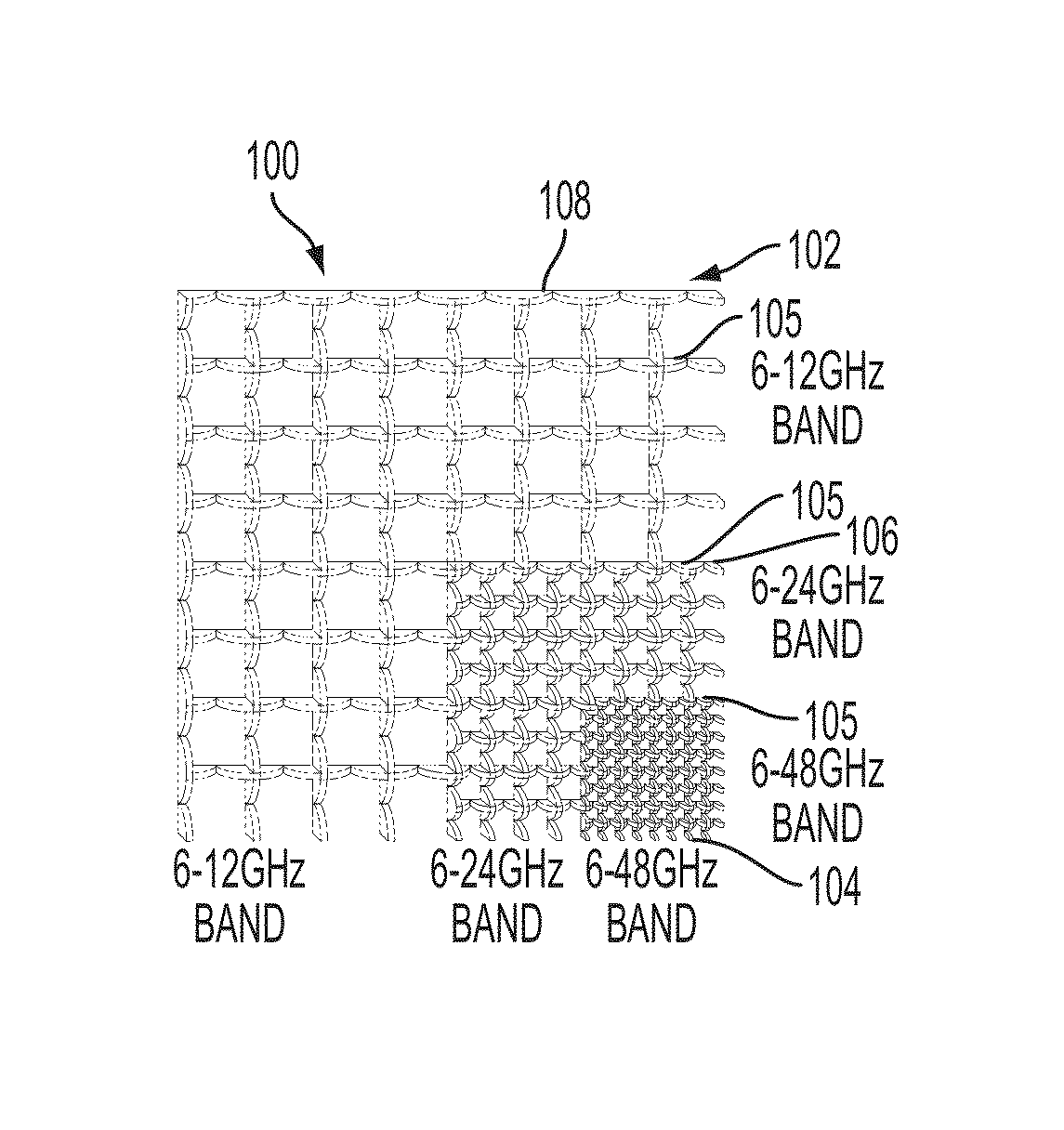
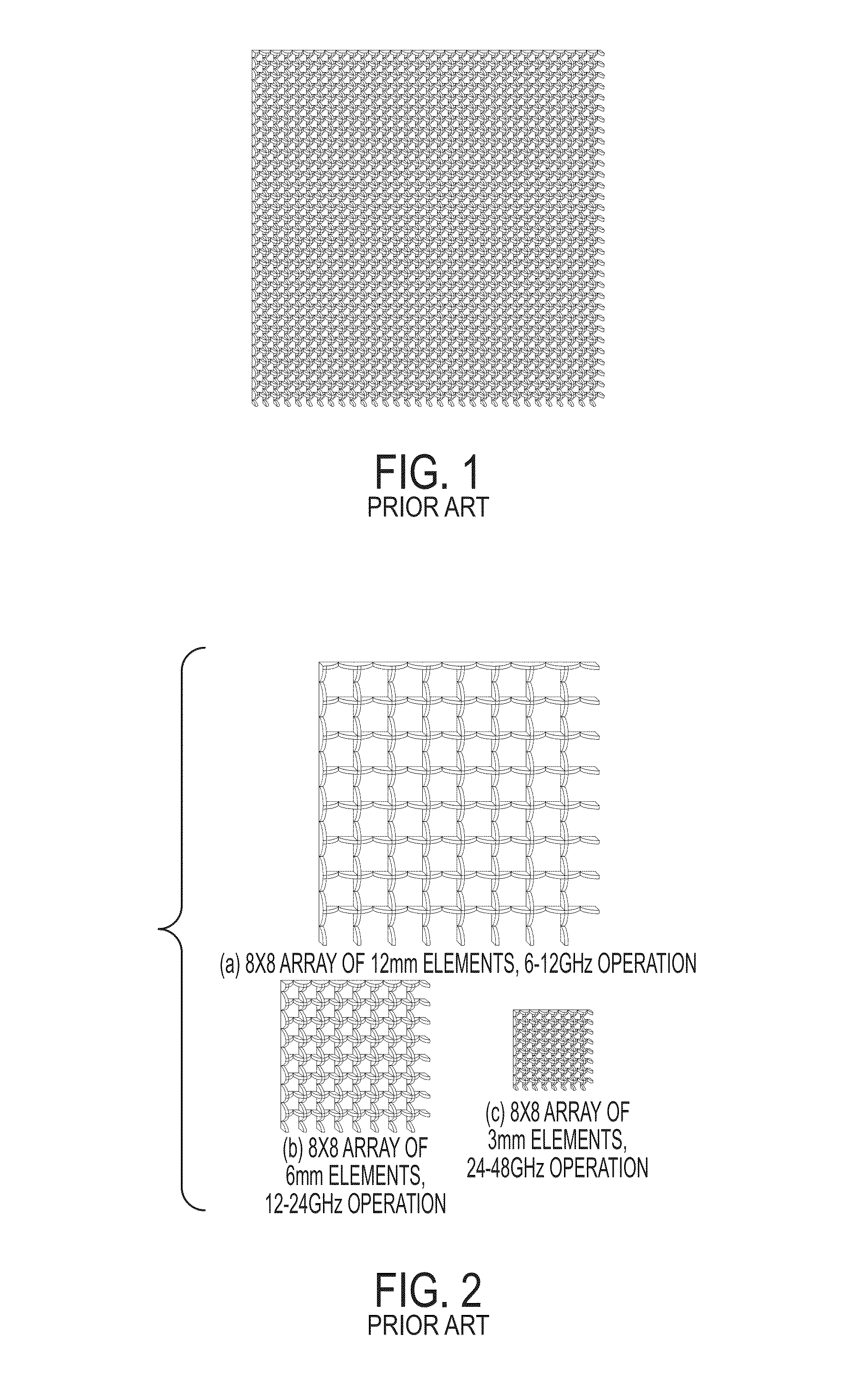
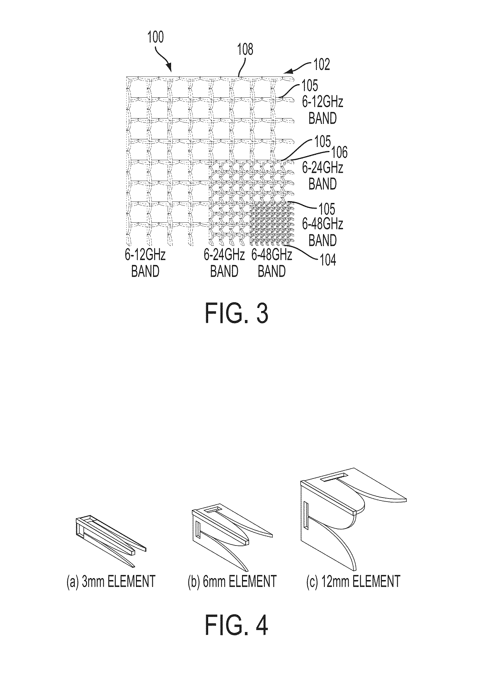
[0030]The following description of the invention assumes a UWB phased array with a 12-degree beamwidth and coverage from 6-48 GHz (8:1 bandwidth), although it should be understood and will be made clear that the invention is not limited to just this embodiment. For reference, we describe first the current state of prior art UWB. For operation at the high end of the frequency band (48 GHz), the requisite array element is roughly 3 mm in width (given typical ½ wavelength lattice spacing requirements). Referring now to FIG. 1, to achieve a 12-degree beamwidth at this frequency in a conventional prior art UWB array, an aperture of roughly four wavelengths is required, or equivalently, an 8×8 array of 3 mm elements. To achieve a 12-degree beamwidth three octaves lower in frequency (12 GHz), an aperture of roughly four wavelengths (and equivalently 100 mm diameter) is required. This equates to an array of 32×32 3 mm-wide elements, with 1,024 elements total (in each polarization).

[0031]Ref...


PUM


Abstract

An ultra-wideband antenna array architecture includes a first array of radiating elements, a second array of radiating elements, and a third array of radiating elements, with their respective element widths proportionately ascending in size. In one configuration, the first array radiating element width is half a wavelength at the highest frequency of operation, the second array element width is twice the first width, and the third array element width is twice the second width. The first, second, and third arrays are positioned in a wavelength-scaled lattice wherein the wavelength scaling is based on design operative frequencies and whereby adjacent actively-radiating elements for an operative frequency are aligned so as to produce constructive interference when powered up. Feed means such as a diplexer with a selected-band frequency control then provides power to each array.

Description

CROSS-REFERENCE TO RELATED APPLICATIONS[0001]This Application claims the benefit of U.S. Provisional Application 61 / 113,936 filed on Nov. 12, 2008, and incorporated herein by reference.FIELD OF THE INVENTION[0002]The present disclosure relates generally to an ultra-wideband antenna array architecture and more particularly to a wavelength-scaled array (WSA) architecture that systematically uses interaligned radiators of different sizes to achieve a single UWB aperture with significantly-reduced element count.BACKGROUND OF THE INVENTION[0003]Multi-functional antenna array apertures for military and commercial use promise a larger number of applications with better performance at lower overall cost, weight, and installation space. A central component in these systems is the ultra-wideband (UWB) phased antenna array. Traditional UWB arrays are very costly to build due to the high element density required for scanning across a wide range of frequencies. In order to make multi-functional ...

Claims


Application Information

Patent Timeline
Patent Type & Authority Patents(United States)
IPC IPC(8): H01Q13/00
CPCH01Q13/08H01Q21/064H01Q5/42H01Q25/00H01Q21/24
Inventor KINDT, RICKIE W.KRAGALOTT, MARKPARENT, MARK GTAVIK, GREGORY C
Owner THE UNITED STATES OF AMERICA AS REPRESENTED BY THE SECRETARY OF THE NAVY
Why Eureka
Try Eureka