
Method and apparatus for controlling radiation direction of small sector antenna

a technology of propagation direction and antenna, applied in electrical equipment, antenna arrays, antennas, etc., can solve the problems of low-power consumption and limited calculation capabilities, complicated calculation, and high power consumption of phased array antennas and wireless communication systems, and achieve low power consumption, simple calculation, and limited power and calculation capabilities.

Active Publication Date: 2013-03-26
ELECTRONICS & TELECOMM RES INST
View PDF16 Cites 176 Cited by
  • Summary
  • Abstract
  • Description
  • Claims
  • Application Information

AI Technical Summary

Benefits of technology

This approach reduces power consumption and simplifies calculations, enabling effective control of radiation direction with minimal power and calculation requirements, suitable for devices with limited capabilities.

Problems solved by technology

However, the phased array antenna and the wireless communication system consume much power, need to have a high calculation capability, and need to include a plurality of RF ports.
In comparison, the small wireless device having a low-power consumption and limited calculation capabilities like the sensor node mostly supports an RF output of a single port and needs to control only the direction of a limited number of sectors.
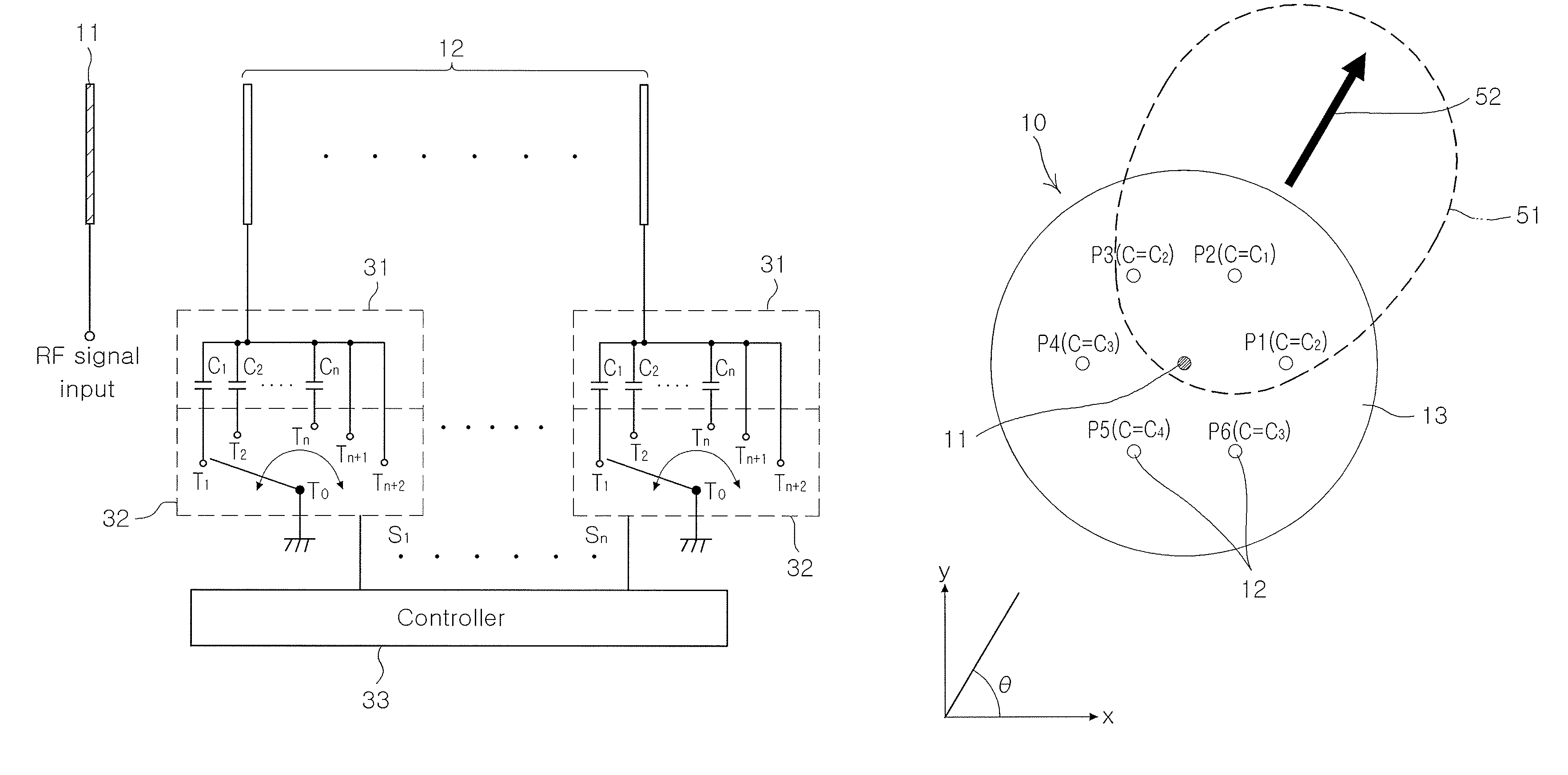
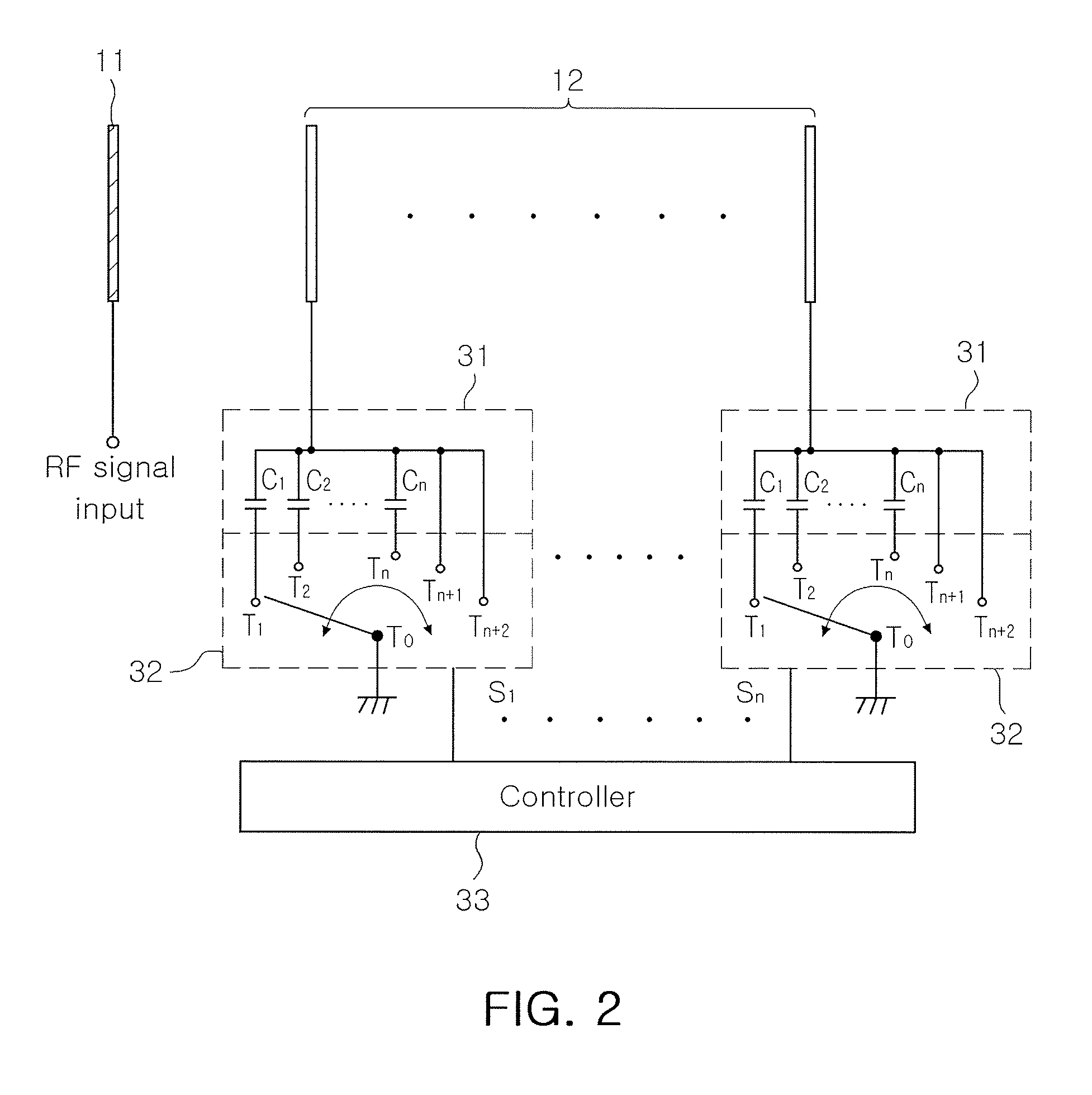
In the related art, a varactor diode is commonly used as a means of controlling the capacitance of the plurality of parasitic elements 12, which, however, disadvantageously accompanies a complicated calculation to appropriately adjust a nonlinear corresponding relationship between a bias voltage and the radiation direction.
In addition, in order to convert a digital bit stream generated according to the complicated calculation into a bias voltage of the varactor diode, a digital-to-analog converter (DAC) must be provided to increase the power consumption.

Method used


Image

  • Method and apparatus for controlling radiation direction of small sector antenna
  • Method and apparatus for controlling radiation direction of small sector antenna
  • Method and apparatus for controlling radiation direction of small sector antenna

Examples


Embodiment Construction

[0028]Exemplary embodiments of the present invention will now be described in detail with reference to the accompanying drawings. The invention may however be embodied in many different forms and should not be construed as limited to the embodiments set forth herein. Rather, these embodiments are provided so that this disclosure will be thorough and complete, and will fully convey the scope of the invention to those skilled in the art. In the drawings, the shapes and dimensions may be exaggerated for clarity, and the same reference numerals will be used throughout to designate the same or like components.

[0029]It will be understood that when an element is referred to as being “connected with” another element, it can be directly connected with the other element or intervening elements may also be present. In contrast, when an element is referred to as being “directly connected with” another element, there are no intervening elements present. In addition, unless explicitly described t...


PUM


Abstract

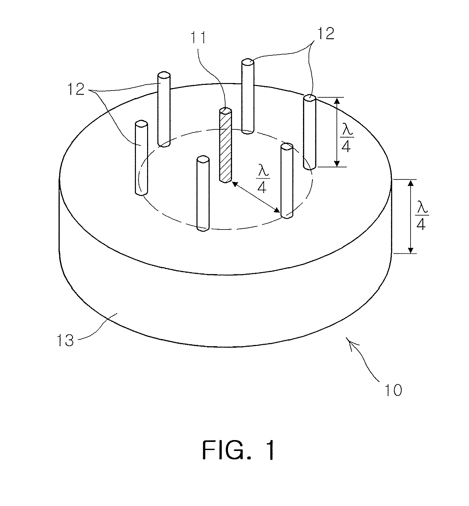
Disclosed are an apparatus and method for controlling a radiation direction of a small sector antenna, used for a small wireless transmission device having limited power and calculation capabilities, capable of operating at a low power consumption with the necessity of simple calculation capabilities or without the necessity of even a few calculation capabilities. The apparatus for controlling a radiation direction of a small sector antenna includes a plurality of capacitance blocks including a plurality of capacitors each having one end commonly connected to corresponding parasitic elements and having a different capacitance. Capacitors having a capacitance corresponding to a radiation direction are selectively connected to corresponding parasitic elements through a plurality of switching units and a controller, thereby simplifying controlling and reducing power consumption for controlling the radiation direction.

Description

CROSS-REFERENCE TO RELATED APPLICATIONS[0001]This application claims the priority of Korean Patent Application No. 10-2008-0129162 filed on Dec. 18, 2008, in the Korean Intellectual Property Office, the disclosure of which is incorporated herein by reference.BACKGROUND OF THE INVENTION[0002]1. Field of the Invention[0003]The present invention relates to an apparatus and method for controlling a propagation direction of a small sector antenna used for a small wireless system having limited power and calculation capacity such as a mobile communications terminal or a sensor node of a sensor network.[0004]2. Description of the Related Art[0005]Unlike an existing network, a wireless sensor network is basically configured to aim at the automatic and remote collection of information, rather than being a means of communication, a configuration which is extensively utilized in various fields of application such as for scientific, medical, military, commercial purposes. The sensor network inc...

Claims


Application Information

Patent Timeline
Patent Type & Authority Patents(United States)
IPC IPC(8): H01Q19/00
CPCH01Q3/446H01Q19/32H01Q3/26H04W16/28
Inventor PARK, JU DERKLEE, KANG WOOPARK, SANG JOON
Owner ELECTRONICS & TELECOMM RES INST
Learn More