
Information processing apparatus and mode switching method

a technology of information processing apparatus and mode switching method, which is applied in the direction of frequency-division multiplex, instruments, high-level techniques, etc., can solve the problems of power consumption, signal line number, signal line number, etc., and achieve the effect of saving power

Inactive Publication Date: 2013-03-26
SONY CORP
View PDF9 Cites 63 Cited by
  • Summary
  • Abstract
  • Description
  • Claims
  • Application Information

AI Technical Summary

Benefits of technology

The patent text describes a new encoding scheme that reduces the number of signal lines needed for communication. By eliminating the need for a PLL (a type of circuit used in communication devices), power consumption is reduced. The encoding scheme also allows for easy extraction of a clock component, which further helps in regenerating the clock at the receiving end. This makes it possible to reduce the number of signal lines needed and decreases power consumption and circuit size. Additionally, the patent text suggests a method for switching between different circuits based on the operational status of the device, which can further lead to power savings. The invention improves power consumption in devices that use both narrow band and broadband communication for internal data transmission.

Problems solved by technology

However, in an information processing apparatus such as a notebook PC, even if the serial transmission method using the above code is used, the number of signal lines wired in the hinge portion is still large.
As described above, a reduction in power consumption as well as a reduction in the number of signal lines is an important issue for a small electronic device typified by the notebook PC, the mobile phone and the like.
However, with this approach, it is difficult to reduce power consumption of a circuit necessary for the operation of the electronic device.

Method used


Image

  • Information processing apparatus and mode switching method
  • Information processing apparatus and mode switching method
  • Information processing apparatus and mode switching method

Examples


embodiment

2. EMBODIMENT

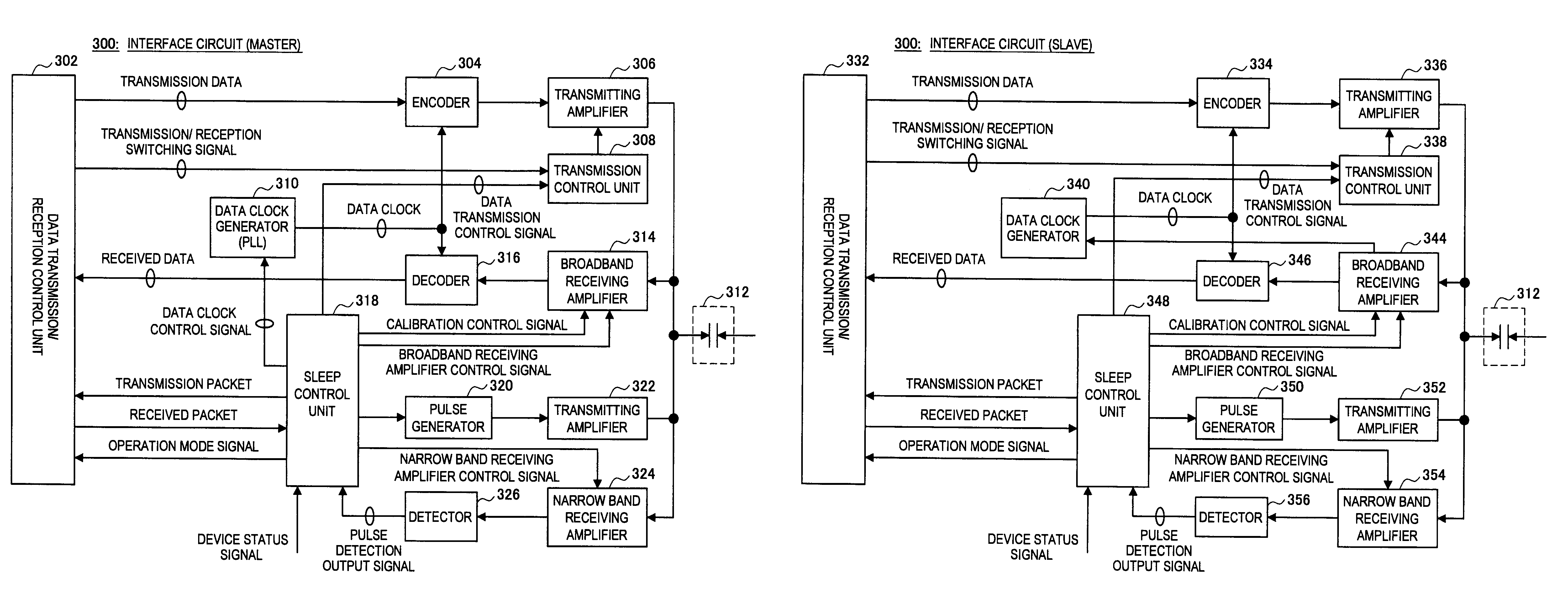
[0159]An embodiment of the present invention will be described. The present embodiment proposes an operation mode switching method that can be applied also to a system according to which it is hard to transmit / receive the interface signal by using a change in the DC level. Hereunder, the operation mode switching method according to the present embodiment and a circuit configuration of an interface circuit 300 capable of realizing the switching method will be described. Additionally, like the interface circuit 200 described above, the interface circuit 300 is a circuit for interfacing the master device and the slave device. Furthermore, it is assumed that broadband receiving means for high-speed data transmission and narrow band receiving means for low-speed data transmission are provided in the interface circuit 300.

[0160](Illustration of Operation Mode)

[0161]First, an operation mode assumed in the present embodiment will be illustrated. However, the application scope o...


PUM


Abstract

Provided is an information processing apparatus which includes a first-module including a first narrow-band communicator for performing narrow band communication with a second-module, a first broadband-communicator for performing broadband communication with the second-module, and a first controller for controlling an operation state of the first broadband-communicator according to an operation mode, and a second-module including a second narrow-band communicator for performing narrow-band communication with the first-module, a second broadband-communicator for performing broadband communication with the first-module, and a second controller for controlling an operation state of the second broadband-communicator according to an operation mode. The first controller places the first broadband-communicator in an operation state in a first mode, and places the first broadband-communicator in a standby state in a second mode. The second controller places the second broadband-communicator in an operation state in the first mode, and places the second broadband-communicator in a standby state in the second mode.

Description

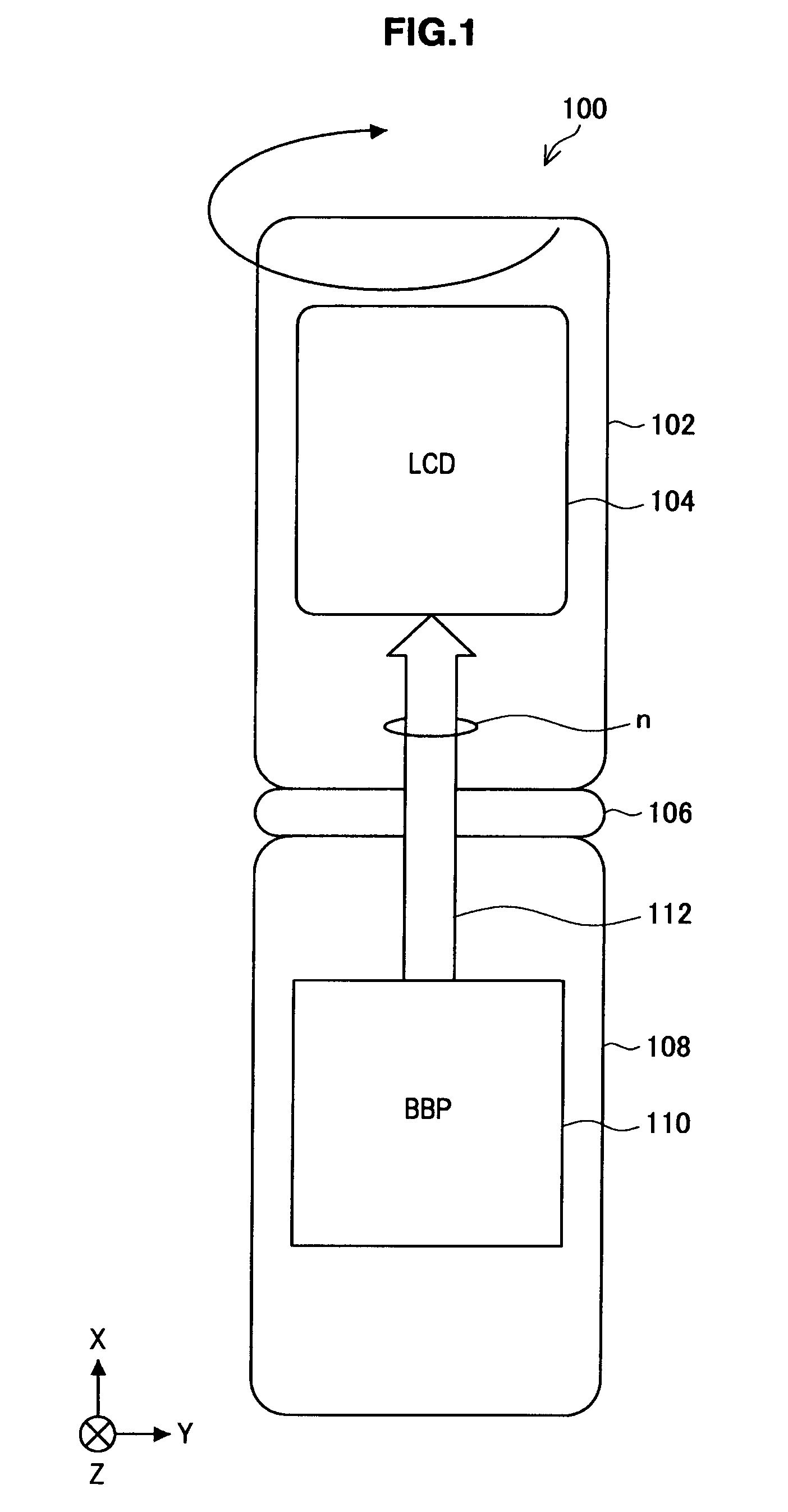
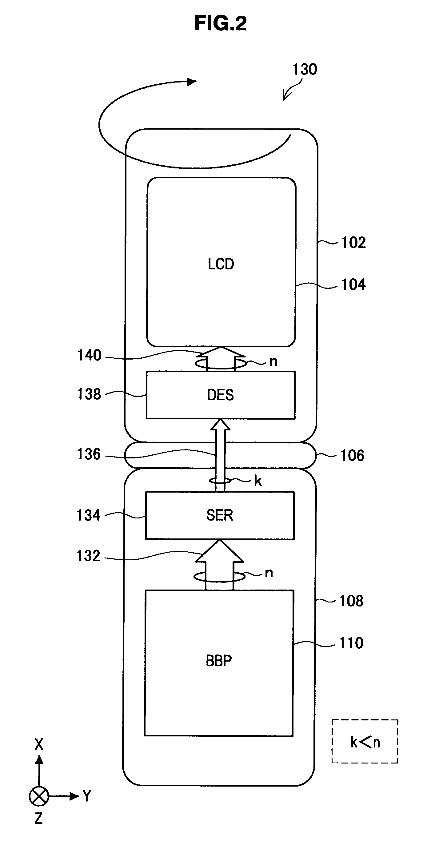
CROSS-REFERENCE TO RELATED APPLICATIONS[0001]The present application contains subject matter related to that disclosed in Japanese Priority Patent Application JP 2009-143205 filed in the Japan Patent Office on Jun. 16, 2009, the entire content of which is hereby incorporated by reference.BACKGROUND OF THE INVENTION[0002]1. Field of the Invention[0003]The present invention relates to an information processing apparatus, and a mode switching method.[0004]2. Description of the Related Art[0005]Most information processing apparatuses such as mobile phone and notebook personal computer (hereinafter, a notebook PC) use a movable member for a hinge portion connecting a main body to be operated by a user and a display portion on which information is displayed. However, a large number of signal lines and power lines pass through the hinge portion, and a method for maintaining reliability of the wiring is desired. Reducing the number of the signal lines passing through the hinge portion comes...

Claims


Application Information

Patent Timeline
Patent Type & Authority Patents(United States)
IPC IPC(8): H04L27/00H04M1/72448H04M1/73
CPCG06F1/3287G06F1/3203Y02B60/1278Y02B60/1282Y02B60/32Y02D10/00Y02D30/50
Inventor SUGITA, TAKEHIROHIDAKA, ISAOSHIMIZU, TATSUO
Owner SONY CORP
Learn More