Mold system for composite molding

a composite molding and mold system technology, applied in the field of molding methods, can solve the problems of not being able to individually perform the compression molding operation of individual mold systems, the clamping operation of primary molding and secondary molding cannot be performed simultaneously and in addition under the same conditions, and the inability to mold a large-sized molded object, etc., to achieve uniform sheet thickness, reduce cavity volume, and reduce distortion

Active Publication Date: 2013-04-02
TEIJINKASEI +1
View PDF29 Cites 7 Cited by
  • Summary
  • Abstract
  • Description
  • Claims
  • Application Information

AI Technical Summary

Benefits of technology

[0013]The aspect of the invention is a method of molding a composite molded article using a first mold member to mold a primary molded article by primary molding, switching a movable mold member holding the primary molded article with a movable mold member positioned with a second mold member, then using a second mold member in which the primary molded article is inserted to mold a secondary molded article by secondary molding, wherein the primary molding and the secondary molding are executed by non-continuous different steps at points of time different from each other, so the compression molding in the composite molding can be effectively executed.
[0014]According to the aspect of the invention, the method performs either of the primary molding and the secondary molding by compression molding reducing a volume of a cavity, so can mold a low distortion composite molded article.
[0015]According to the aspect of the invention, when performing the compression molding, the method controls a plurality of clamping devices to control compression to hold the movable mold member and first mold member or second mold member parallel, so can mold a composite molded article having a uniform sheet thickness and having a high precision.
[0016]The aspect of the invention is also a mold system for composite molding comprising a first mold member, second mold member, and movable mold member, wherein the movable mold member is positioned to enabling switching between the first mold member and the second mold member and is provided freely engagable / disengagable with the first mold member and the second mold member by a clamper, so can effectively perform the compression molding in the composite molding without requiring a large sized injection molding machine.
[0017]According to the aspect of the invention, the clamper connects and engages the movable mold member and one of the first mold member and the second mold member and engages the other with a gap, so the compression molding can be effectively executed in either of the first mold member and the second mold member.

Problems solved by technology

Therefore, a large sized fixed platen and movable platen become necessary and the shape of the injection molding machine also becomes larger, so this is not suitable for molding a large sized molded article.
According to the technology of Patent Document 1 explained above, however, the clamping operations of the primary molding and secondary molding can only be performed simultaneously and in addition under the same conditions.
Therefore, it is substantially impossible to individually perform the compression molding operations by individual mold systems.
Therefore, the problem of the larger size of the injection molding machine in Patent Document 1 explained above is solved, but the problem of compression molding being impossible is not solved.

Method used


Image

  • Mold system for composite molding
  • Mold system for composite molding
  • Mold system for composite molding

Examples


Embodiment Construction

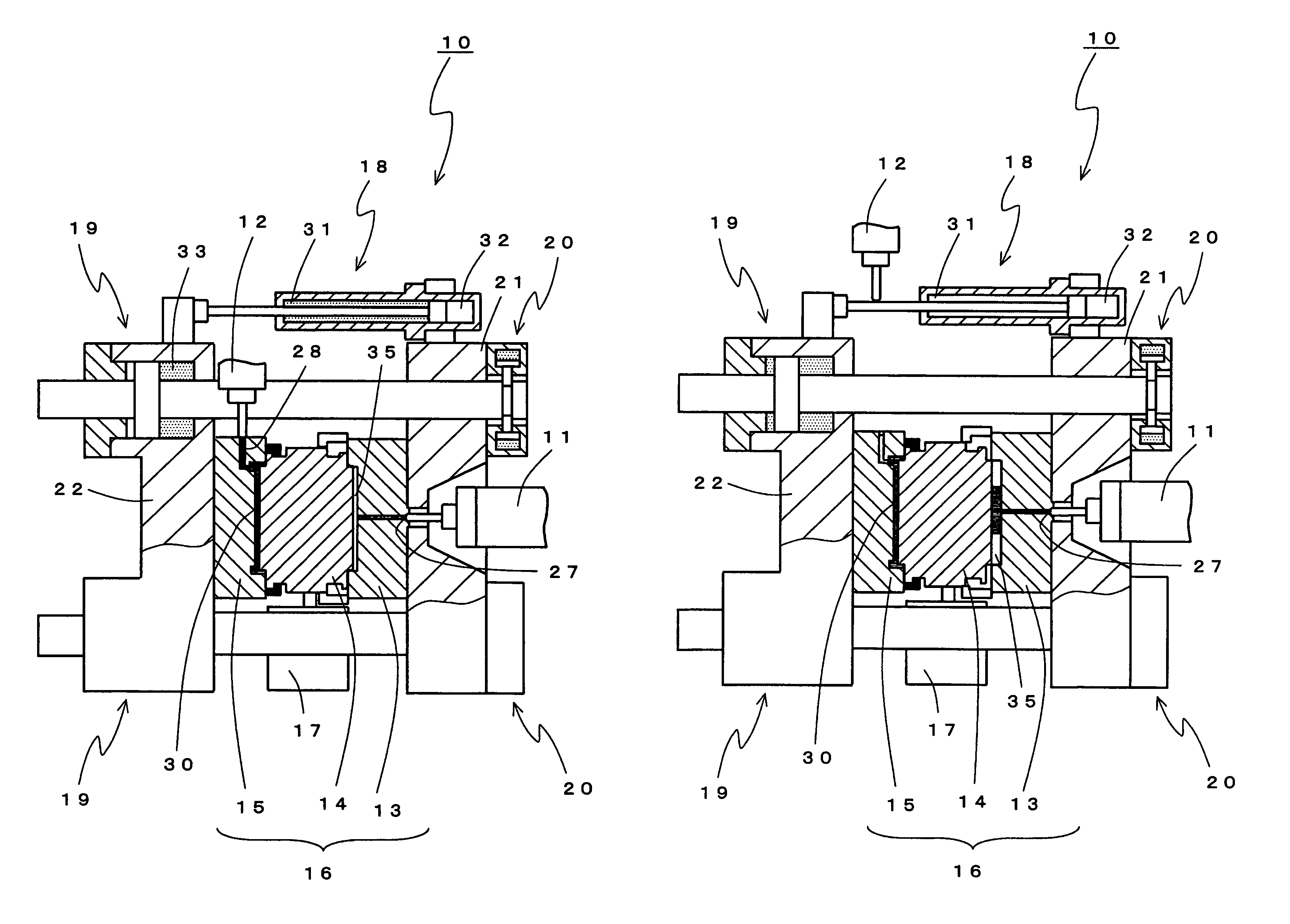
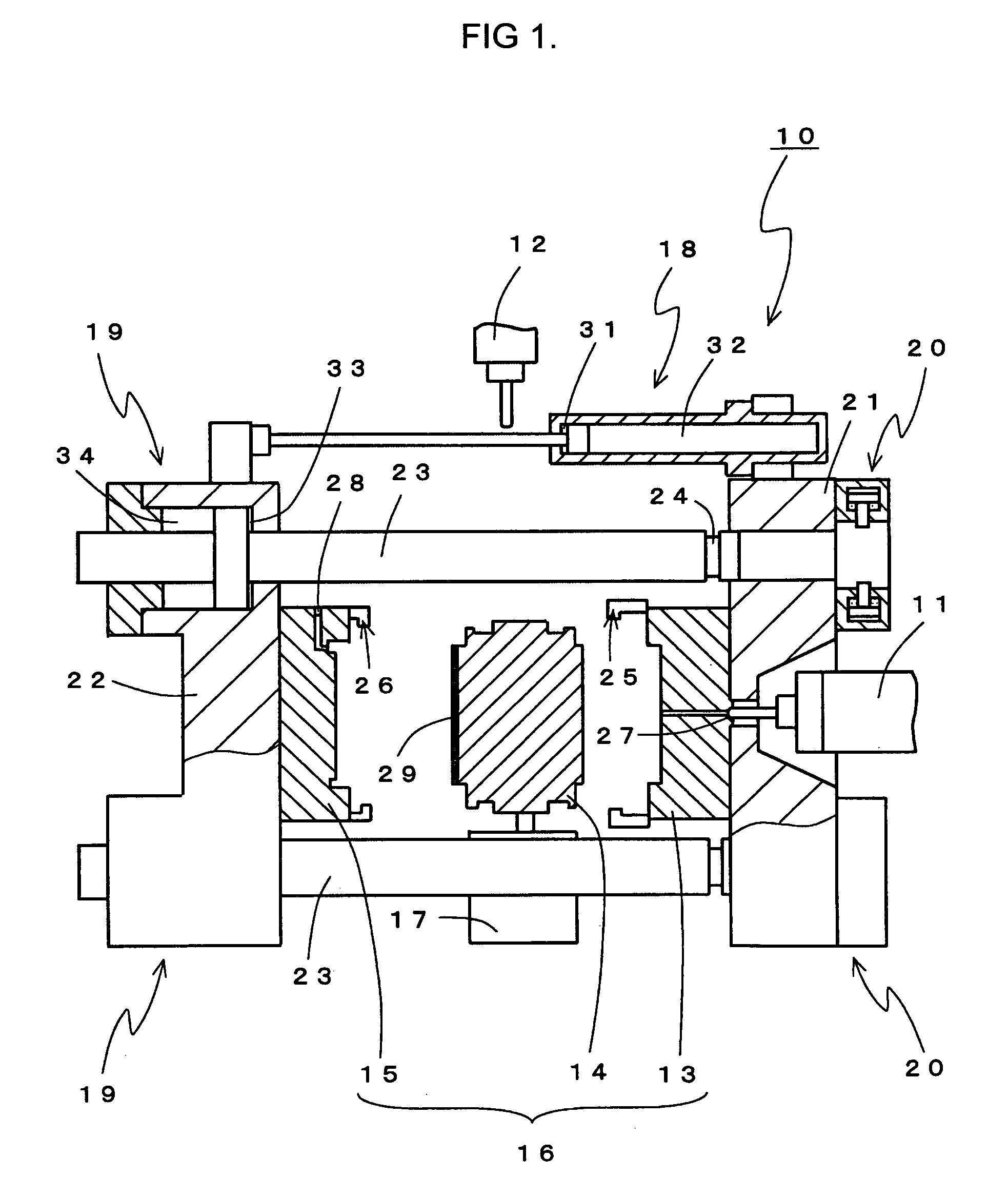
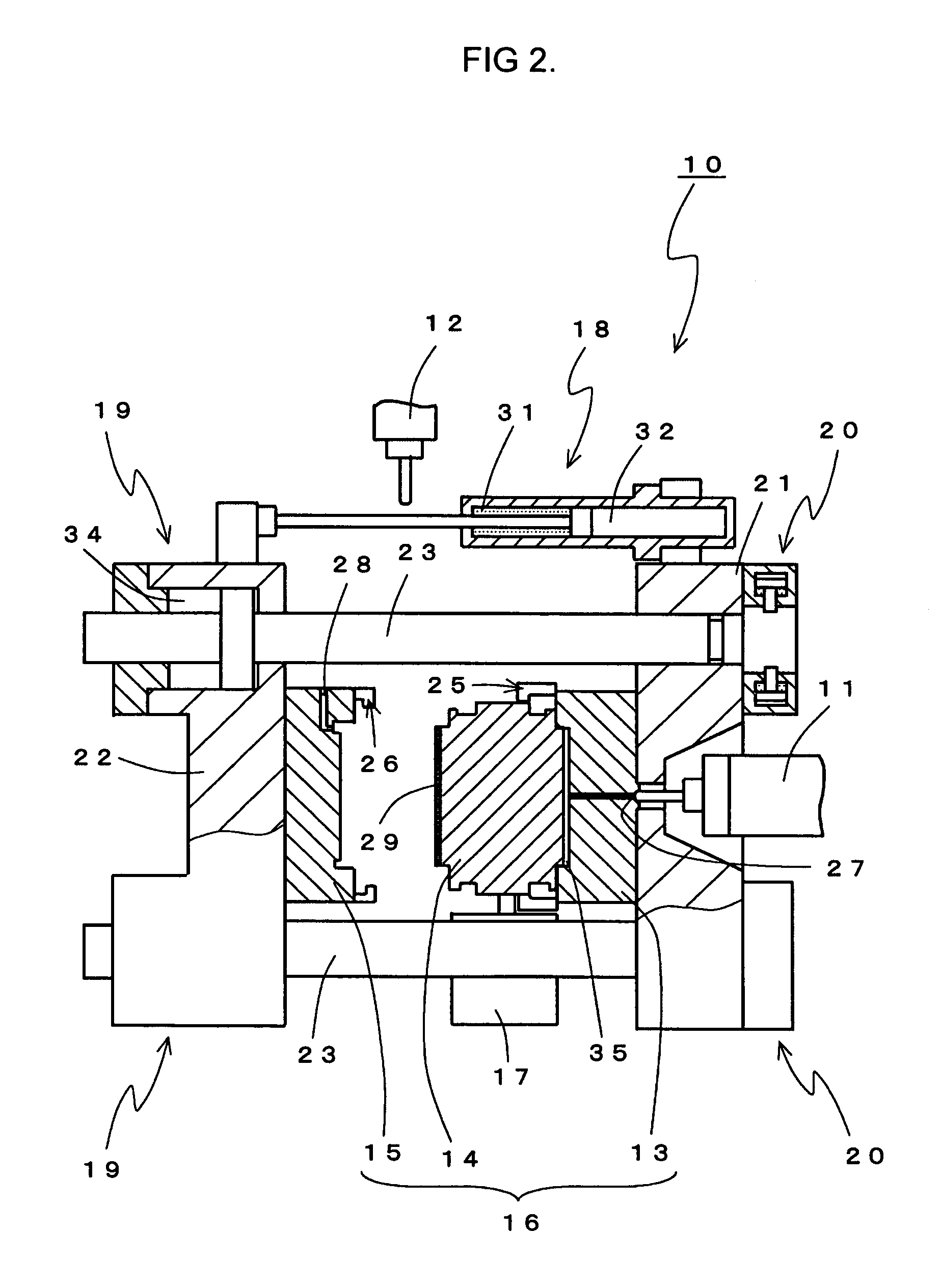
[0018]An embodiment of the present invention will be explained in detail based on the drawings. FIG. 1 is a vertical sectional view of a clamping device showing a state where a movable mold rotates after primary molding and then starts secondary molding, FIG. 2 is a vertical sectional view of a clamping device showing a state of closing the mold for secondary molding, FIG. 3 is a vertical sectional view of a clamping device showing a state where the mold closing is completed and mold clamping is prepared for, FIG. 4 is a vertical sectional view of a clamping device showing a state where the mold is clamped and the secondary molding is carried out, FIG. 5 is a vertical sectional view of a clamping device showing a state where the mold is opened for the primary molding and the compression molding is prepared for, FIG. 6 is a vertical sectional view of a clamping device showing a state where the injection of the primary molding is carried out, FIG. 7 is a vertical sectional view of a c...


PUM

PropertyMeasurementUnit
volumeaaaaaaaaaa
shapeaaaaaaaaaa
thicknessaaaaaaaaaa

Abstract

[PROBLEM]To provide a method of molding a composite molded article enabling compression molding without requiring a large sized injection molding machine and a mold system used for that.[MEANS FOR SOLUTION]A method of molding a composite molded article using a first mold member 13 to mold a primary molded article 29 by primary molding, switching a movable mold member holding the primary molded article 29 with a movable mold member 14 positioned with a second mold member 15, then using a second mold member 15 in which the primary molded article 29 is inserted to mold a secondary molded article 30 by secondary molding, wherein the primary molding and the secondary molding are executed by non-continuous different steps at points of time different from each other.

Description

TECHNICAL FIELD[0001]The present invention relates to a molding method using a mold system comprising a first mold member, second mold member, and movable member to compression mold a composite molded article.BACKGROUND ART[0002]As art relating to a method and mold system for injection molding a composite product made of resins of different properties, there are an injection molding method of a composite product and a mold system for injection molding a composite product (see for example Patent Document 1). This Patent Document 1 uses a primary molding unit to mold a primary molded part by primary molding, switches a movable mold holding the primary molded part with a movable mold of a secondary molding unit, and uses a secondary molding unit having the primary molded part as an insert to mold a secondary molded part by secondary molding and thereby simultaneously proceed with the primary molding and secondary molding.[0003]According to the injection molding method and mold system o...

Claims


Application Information

Patent Timeline
Patent Type & Authority Patents(United States)
IPC IPC(8): B29C45/14B29C43/20B29C43/18B29C45/16B29C69/02
CPCB29C45/045B29C45/1628B29C45/561B29C43/04B29L2011/00B29L2031/3055B29L2031/7782
Inventor FUKUMOTO, KENJIJINNO, SHIZUOTSUKAMOTO, ATSUSHIHOTAKA, TOSHIAKIKONDO, FUMITAKASUGIHARA, YASUHIROHISAKI, KAZUMA
Owner TEIJINKASEI
Why Eureka
Try Eureka