Method and apparatus for producing hydrogen and oxygen gas

a technology of hydrogen and oxygen gas and apparatus, applied in the field of electrolysis of water, can solve the problems of loss of plasma generating conditions, no longer operating the electrolysis process on the basis of plasma electrolysis, etc., and achieve the effect of reducing the effect of turbulen

Inactive Publication Date: 2013-04-02
HOPE CELL TECH
View PDF4 Cites 7 Cited by
  • Summary
  • Abstract
  • Description
  • Claims
  • Application Information

AI Technical Summary

Benefits of technology

[0028]By forming the cathode as a body of an electrolysis cell, the plasma generated between the cathode and anode is encouraged to spatially disperse away from the points of closest geometrical proximity between the anode and the cathode, thereby assisting to spatially distribute the plasma around the electrolysis cell.
[0030]Preferably, the two or more further electrodes are located in close proximity to the cathode so the second electrical potential applied to the two or more further electrodes encourages plasma generated between the cathode and the anode to transfer to between the further electrodes and the anode.
[0035]Preferably, step (c) involves applying a second electrical potential to two or more further electrodes in contact with the electrolyte and in close proximity to the first electrodes, the second electrical potential generating an electrical field to cause plasma generated between the cathode and the anode to transfer from the cathode to two or further electrodes to stabilise the plasma.
[0043]Preferably, the two or more further electrodes include an array of apertures for increasing the surface area of the electrode to enhance spatial distribution of plasma.
[0045]Preferably, the apparatus includes an electrolyte flow member for reducing the effect of turbulence caused by gas bubbles moving around the further electrodes.
[0046]Preferably, the electrolyte flow member defines a first channel within the cell for enabling gas bubbles to rise through electrolyte when contained within the cell and a second channel that enables relatively quiescent electrolyte to flow into the first channel, thereby assisting to displace gas bubbles from the further electrodes.

Problems solved by technology

As a result, plasma generating conditions are lost and the electrolysis process no longer operates on the basis of plasma electrolysis until the plasma generating electrodes cool sufficiently to form a screen layer of alkaline ions.

Method used


Image

  • Method and apparatus for producing hydrogen and oxygen gas
  • Method and apparatus for producing hydrogen and oxygen gas
  • Method and apparatus for producing hydrogen and oxygen gas

Examples


Embodiment Construction

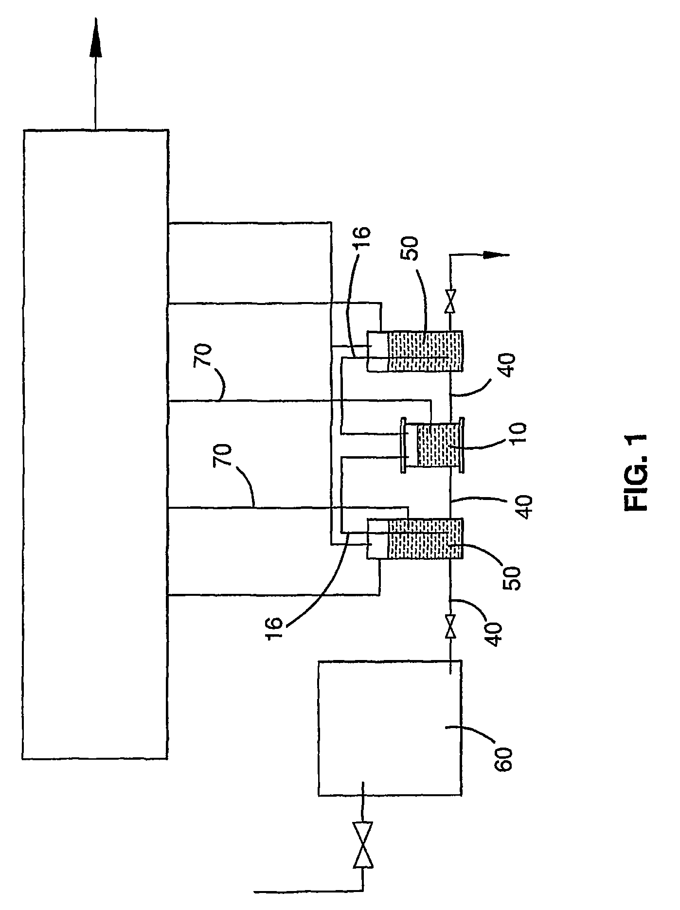
[0055]An electrolysis process in accordance with the present invention may be performed with the apparatus illustrated in FIG. 1.

[0056]The apparatus comprises an electrolysis cell 10 linked to gas separators 50 by electrolyte conduits 40 and off-gas lines 16. The separators 50 are linked to an electrolyte reservoir 60 by a further electrolyte conduit 40 to ensure that the separators remain filled with electrolyte. Thermocouples 70 are located respectively in the cell 10 and in a separator 50 to monitor the temperature of the electrolyte. Although not shown in FIG. 1, two separate power sources provide electrical energy for the electrolysis process.

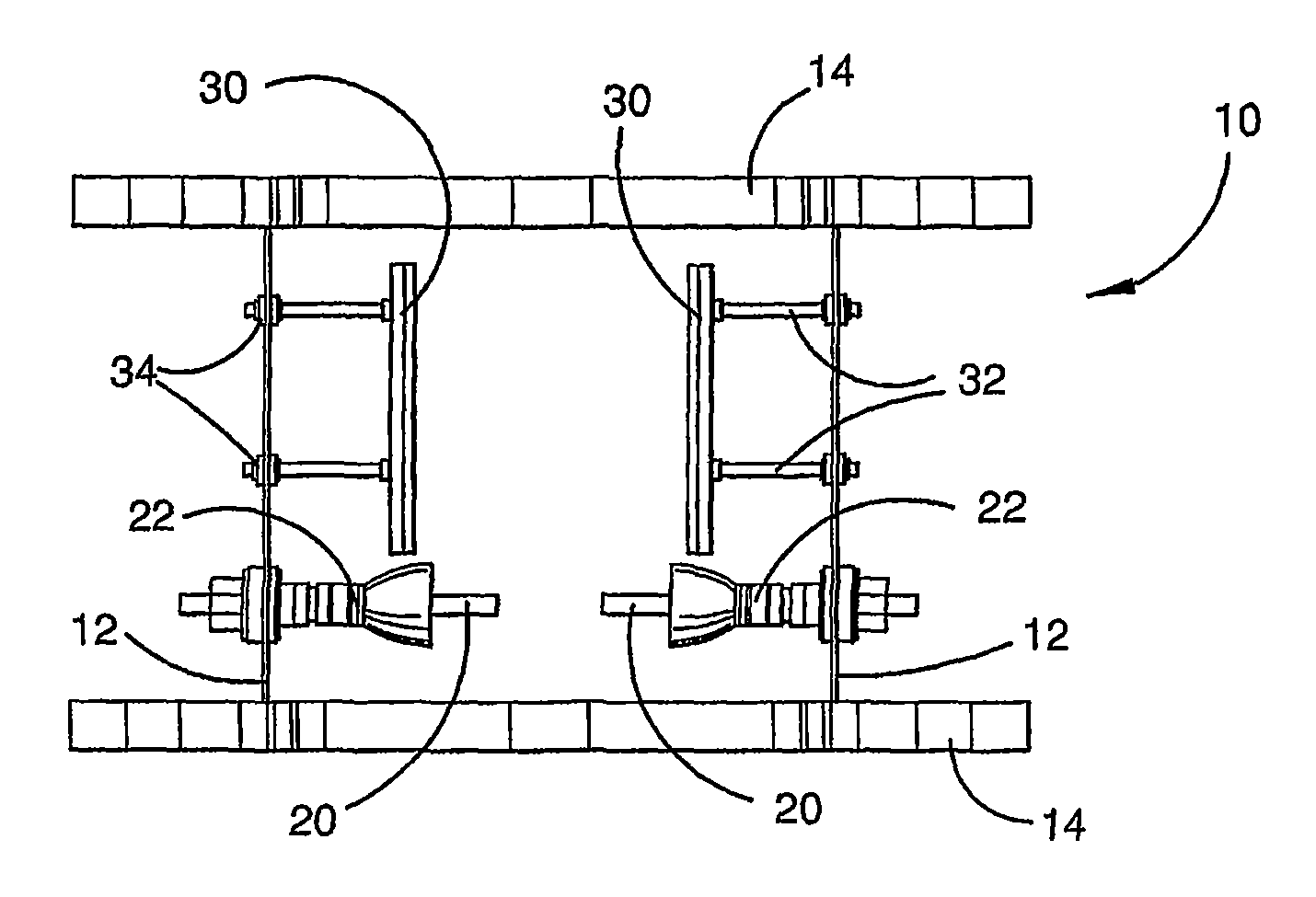
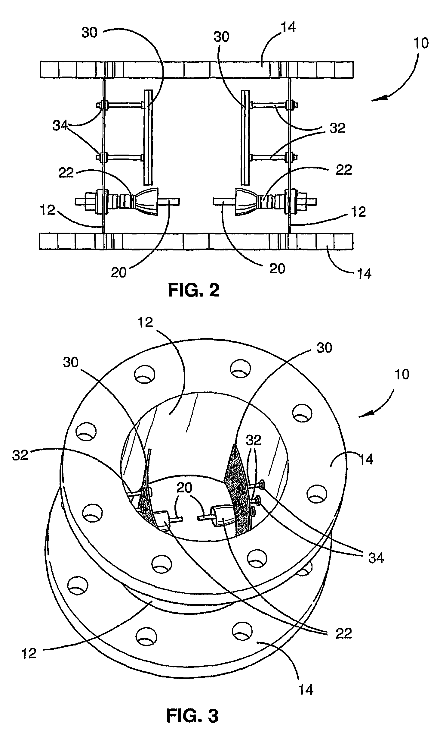
[0057]The cell 10 (as shown in FIG. 2) comprises a hollow cylindrical body 12 with outwardly extending flanges 14 at each end of the body 12. The flanges 14 enable covers (not shown) to be fastened to each end of the body 12 with intermediate gaskets to form a closed volume within the cylindrical body 12 that is air-tight and water-tight.

[...


PUM

PropertyMeasurementUnit
electrical potentialaaaaaaaaaa
currentaaaaaaaaaa

Abstract

This invention relates to a process and an apparatus for generating hydrogen and oxygen gas by electrolysis of water. The process involves forming an electrolyte including alkaline ions and the water and generating plasma between electrodes immersed in the electrolyte by applying an electrical potential between the electrodes. The plasma ionizes the electrolyte, thereby generating hydrogen and oxygen gas. The process further involves controlling the process by relocating the generated plasma between two or more further electrodes.

Description

[0001]This application is a U.S. National Phase Application of PCT International Application No. PCT / AU2008 / 000693, filed May 16, 2008.FIELD OF THE INVENTION[0002]The present invention relates to electrolysis of water for producing hydrogen and oxygen gas.BACKGROUND OF THE INVENTION[0003]Electrolysis technology is increasingly being adopted as a method of generating hydrogen and oxygen where there is a demand for hydrogen / oxygen fuel for combustion or hydrogen fuel cells. One driving force behind this trend is a shift away from fossil fuels as an energy source.[0004]The main types of electrolysis involve alkaline solutions and proton-exchange membranes. While both are proven technologies, they have limited conversion efficiency (i.e. the energy produced versus the energy input to drive the process) of less than 90%. Additionally, there is an initial high capital cost so applications generally are limited to specialist purposes.[0005]A technical paper by Mizuno et. al., entitled “Con...

Claims


Application Information

Patent Timeline
Patent Type & Authority Patents(United States)
IPC IPC(8): C25B1/02C25C1/02
CPCC01B3/042C25B1/04C25B15/00Y02E60/364Y02E60/366Y02E60/36
Inventor VANCINA, ROBERT
Owner HOPE CELL TECH
Why Eureka
Try Eureka