Electrical switch

a technology of electric switches and switches, applied in the direction of electric switches, electrical equipment, contacts, etc., can solve the problems of contact system failure, contact system failure, contact system failure, etc., and achieve the effect of increasing the operation reliability of the switch

Active Publication Date: 2013-04-02
MARQUARDT GMBH SCHLOSSTRASSE 16 7201 RIETHEIM-WEILHEIM 1 WEST GERMANY
View PDF9 Cites 17 Cited by
  • Summary
  • Abstract
  • Description
  • Claims
  • Application Information

AI Technical Summary

Benefits of technology

[0008]In the switch according to the invention, the contact system is configured as a spring-action contact system, whereby the contact system is switched over with a snap-action movement. Damaging oscillations and / or creeping switching movements between the switched-on state and the switched-off state of the contact system, which may occur primarily in the event of high loads, severe stresses, vibrations, impacts or the like, are avoided with the switch according to the invention, whereby the operational reliability of said switch is increased. In a particularly preferred configuration, therefore, an electrical switch for electric tools in the AC and / or DC sector, i.e. an electric tool switch with an open-loop or closed-loop control function in the manner of an “accelerator function”, is provided which has a spring-action contact system for relieving the load on and / or for protecting the bridging contact from loads, in particular from teasing of the contact system.
[0010]Preferably, the contact system configured as a spring-action contact system is the bridging contact system for the control device. The actuating mechanism has a switching effect on this contact system in the final position, with the result that this contact system is switched on so as to apply the full voltage to the electric motor. Since the full voltage for the electric tool is therefore applied to the bridging contact system, particularly effective protection from premature destruction of this contact system which is subjected to high electrical loads is thus provided.
[0011]The switch can additionally have a further contact system. This further contact system serves to switch on the voltage supply for the control device by virtue of the actuating mechanism having a switching effect on the further contact system when it is adjusted out of the initial position. When the contact system is switched on, the control device is then operated in such a way that a reduced voltage, depending on the adjustment path of the actuating mechanism, is applied to the electric motor by means of the control device. In a known manner, the reduced voltage may be a pulse width modulation (PWM) for a DC electric motor or phase gating and / or phase chopping control for an AC electric motor, whereby the electric motor is operated at the speed corresponding to the corresponding signal from the signaling device, for example. This further contact system is less susceptible owing to the relatively low voltage to be switched and the relatively low electrical loading and can therefore have a conventional configuration.
[0014]The advantages achieved with the invention consist in particular in that the contact system is protected against premature failure and therefore its life and the operational reliability for the switch is increased. In particular, the bridging contact is protected against failure as a result of particular stresses, for example owing to teasing under vibration. The use of the snap-action switching contact system in an electronic switch with open-loop and / or closed-loop control function for AC and / or DC operation in an electric tool enables particular protection of the contact system while maintaining or without dispensing with the metered runup and / or ramp-up characteristic for the electric motor of the electric tool.

Problems solved by technology

It has been shown with the known switch that the contact system can fail prematurely.
In particular, in switches using open-loop or closed-loop control electronics when using electric tools which are subject to severe stress, the contact system, to be precise primarily that for the bridging contact, can be caused to fail.

Method used


Image

  • Electrical switch
  • Electrical switch
  • Electrical switch

Examples


Embodiment Construction

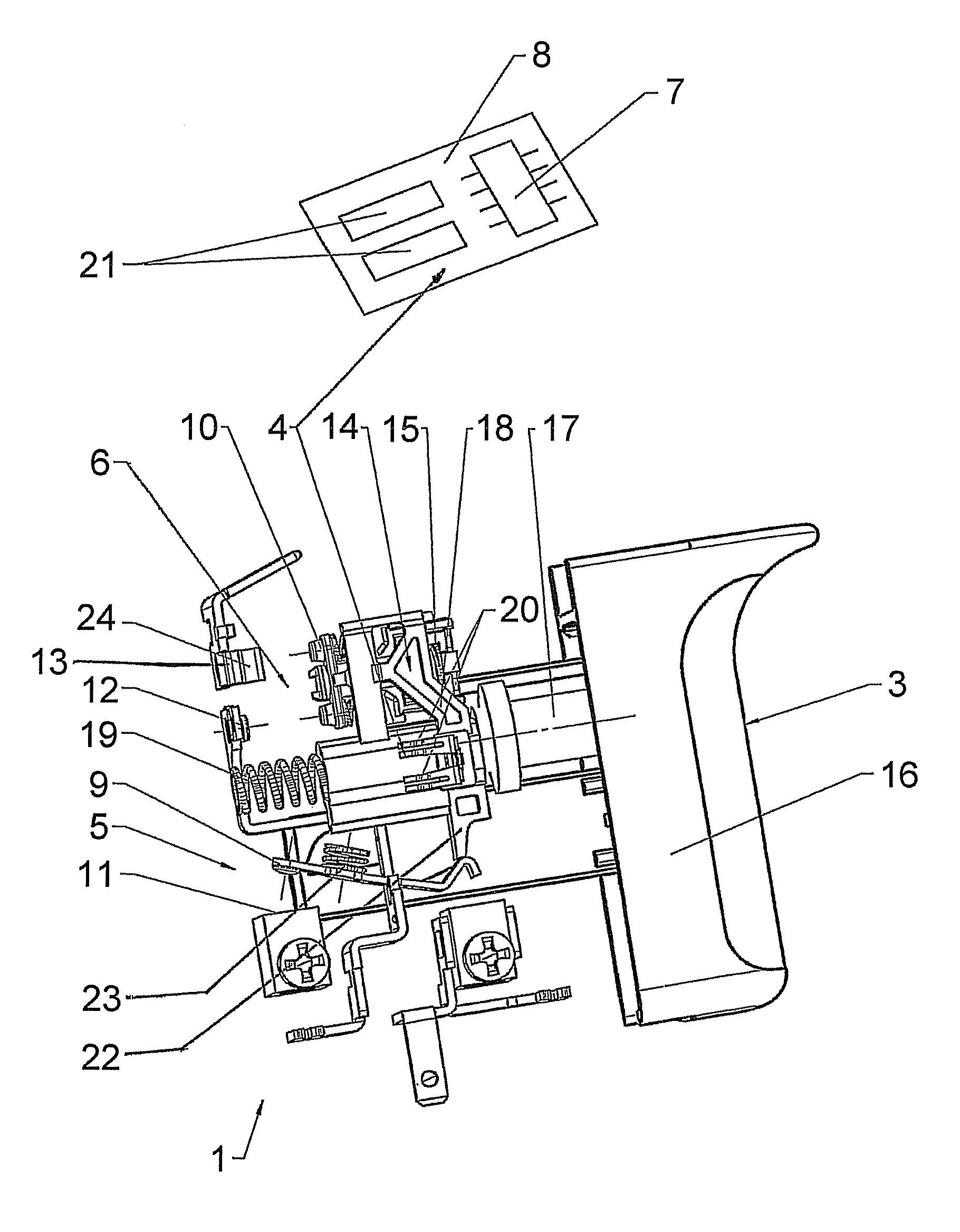
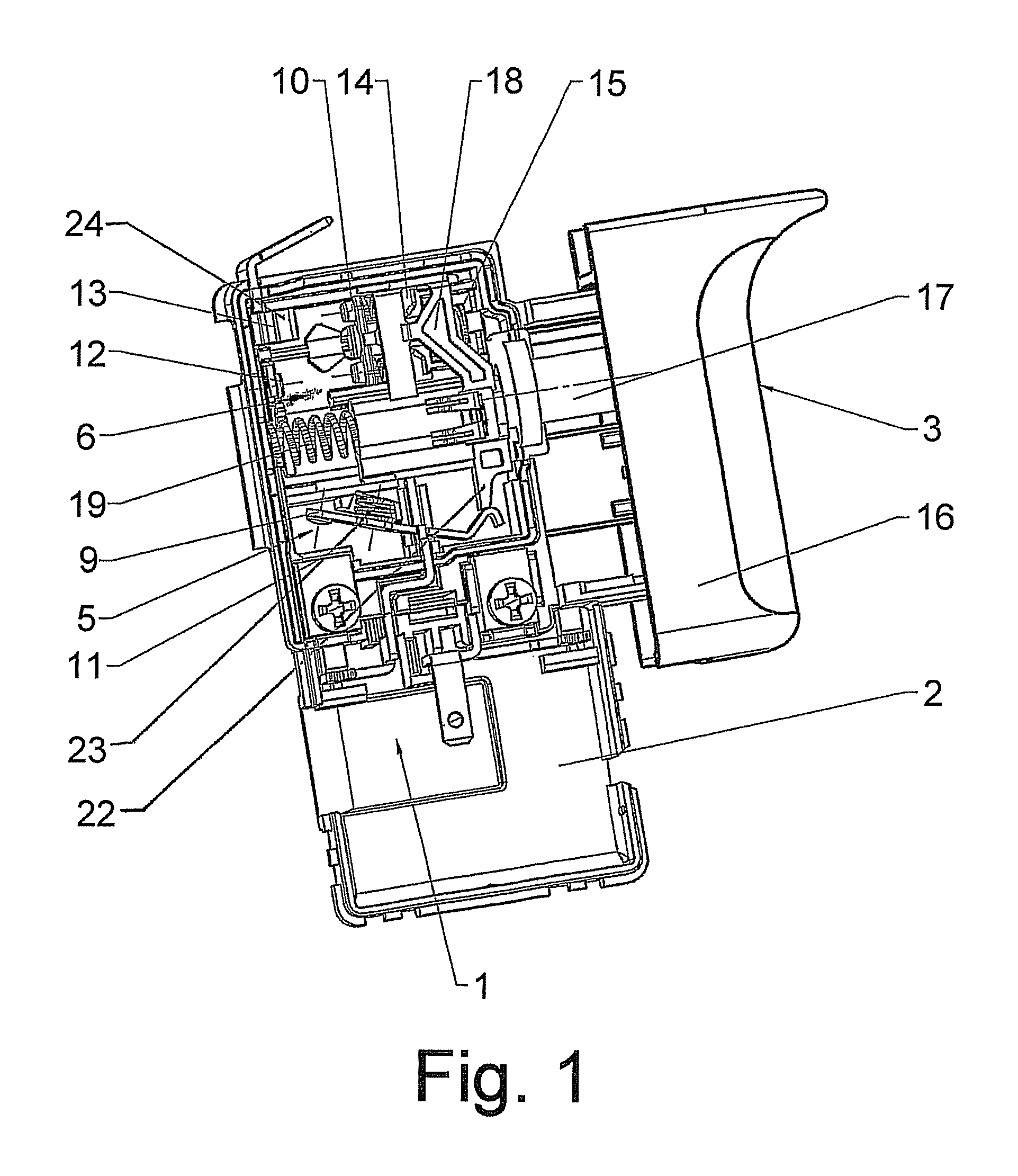
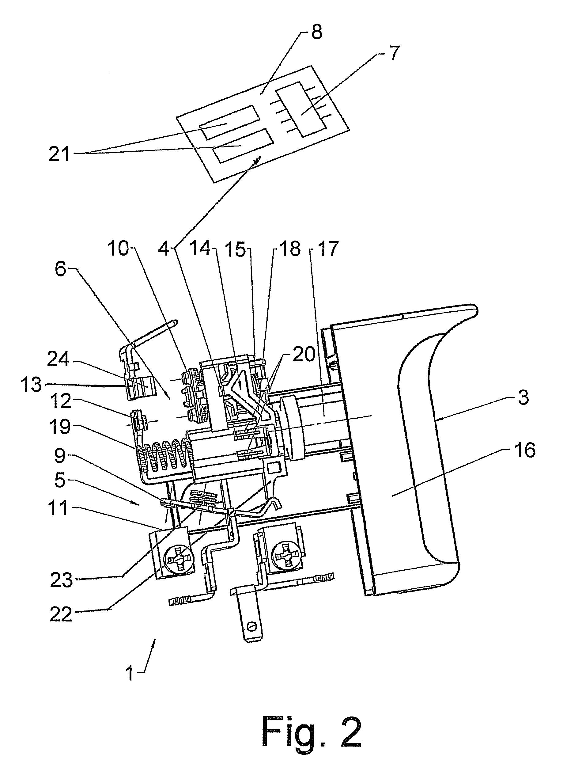
[0018]FIG. 1 shows an electrical switch 1 for an electric tool with an electric motor, such as for an electric drill, a hammer drill, an electric screwdriver or the like. The switch 1 has a housing 2 and an actuating mechanism 3, which can be adjusted by the user manually between an initial position and a final position. The actuating mechanism 3 is operatively connected to a signaling device 4 (shown schematically in FIG. 2) for generating a signal associated with the adjustment path of the actuating mechanism 3. In other words, for example, the value, the magnitude, the nature or the like of the signal corresponds to the adjustment path of the actuating mechanism 3. A contact system 5, 6 is located in the housing 2, with the actuating mechanism 3 having a switching effect on the respective contact system 5, 6 in a respective position, i.e. when the respective movement position is reached and / or left. The actuating mechanism 3 comprises a pushbutton 16 as the operating lever for ma...


PUM


Abstract

An electrical switch for an electric tool with an electric motor including an actuating mechanism which can be adjusted between an initial position and a final position. The switch has a signaling device, which is operatively connected to the actuating mechanism, for generating a signal associated with the adjustment path of the actuating mechanism. The switch has a contact system, with the actuating mechanism having a switching effect on the contact system in one position, whereby the contact system is configured as a spring-action contact system.

Description

CROSS REFERENCE TO RELATED APPLICATIONS[0001]This application is a continuation of International Application No. PCT / DE2010 / 000045 filed Jan. 19, 2010, which designated the United States, and claims the benefit under 35 USC §119(a)-(d) of German Application No. 10 2009 005 384.0 filed Jan. 21, 2009, the entireties of which are incorporated herein by reference.FIELD OF THE INVENTION[0002]The invention relates to an electrical switch.BACKGROUND OF THE INVENTION[0003]Such switches are used for electric tools, for example for handheld electric tools, such as electric drills, hammer drills, electric screwdrivers or the like.[0004]The electrical energy from the power supply system or a suitable rechargeable battery system is converted or influenced with the aid of the electrical switch in such a way that an electric motor for the electric tool, said electric motor being arranged downstream of the switch, is driven as determined by the operator. Thus, for example, the electric motor is swi...

Claims


Application Information

Patent Timeline
Patent Type & Authority Patents(United States)
IPC IPC(8): H01H13/02
CPCH01H9/061
Inventor NIKLEWSKI, GERHARDSTEIDLE, ALFONSHAFEN, DANIEL
Owner MARQUARDT GMBH SCHLOSSTRASSE 16 7201 RIETHEIM-WEILHEIM 1 WEST GERMANY
Why Eureka
Try Eureka