Support bar for turbine diaphragm that facilitates reduced maintenance cycle time and cost

a technology of support bars and turbine diaphragms, which is applied in the direction of machines/engines, stators, liquid fuel engines, etc., can solve the problems of affecting the maintenance cycle time and cost of steam turbines, the typical maintenance process of turbine diaphragms may take several shifts or days to complete, and the support bars cannot be easily removed from the turbine diaphragm, etc., to achieve the effect of less man hours

Active Publication Date: 2013-04-09
GENERAL ELECTRIC CO
View PDF12 Cites 4 Cited by
  • Summary
  • Abstract
  • Description
  • Claims
  • Application Information

AI Technical Summary

Benefits of technology

[0004]The turbine diaphragm maintenance cycle time would be faster and require less man hours if the rotor and diaphragm lower half did not have to be removed to be able to vertically adjust the diaphragm. It may also be desirable to remove the lower half of the diaphragm from the turbine casing without having to remove the rotor during the turbine diaphragm maintenance process or during vertical alignment of the diaphragm.

Problems solved by technology

Current support bar designs have been found to hinder the maintenance cycle time and cost of a steam turbine because these designs require that the rotor and diaphragm lower half be removed in order to perform vertical diaphragm alignment or maintenance on the turbine diaphragm.
As a result, a typical turbine diaphragm maintenance process may take several shifts or days to complete.
The support bars cannot readily be removed from the turbine diaphragm without removing the diaphragms from the turbine casing because there is not enough clearance to get to the horizontal bolts that are used to horizontally secure the support bars to the lower half of the diaphragm.
The fact that the support bars cannot be removed from the diaphragms while in the turbine casing means that the adjustment shim blocks also cannot be removed, therefore, preventing vertical adjustment of the diaphragm within the turbine casing.

Method used


Image

  • Support bar for turbine diaphragm that facilitates reduced maintenance cycle time and cost
  • Support bar for turbine diaphragm that facilitates reduced maintenance cycle time and cost
  • Support bar for turbine diaphragm that facilitates reduced maintenance cycle time and cost

Examples


Embodiment Construction

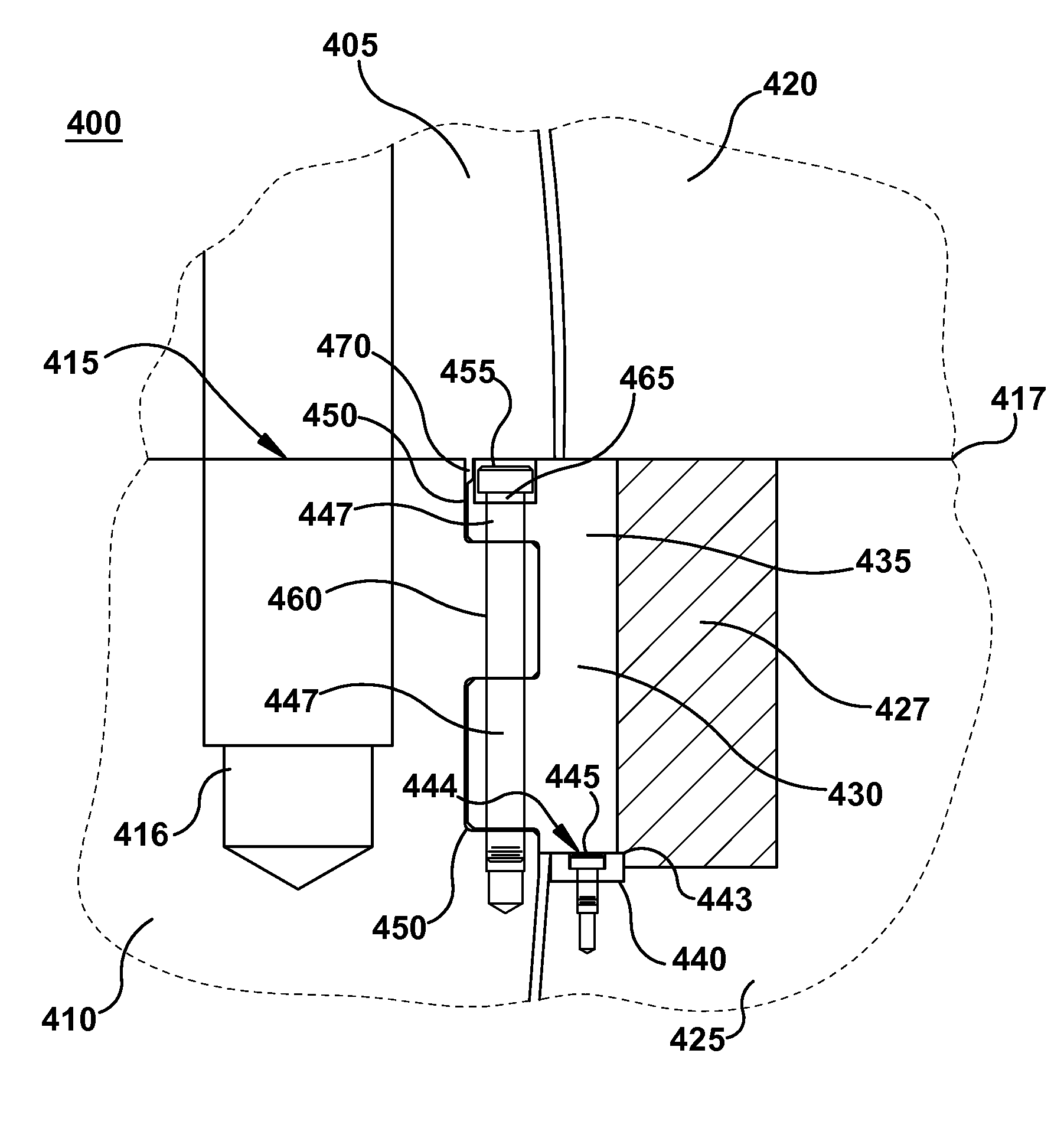
[0015]Various embodiments of the present invention are directed to a support bar arrangement that is secured to the turbine diaphragm (hereinafter “diaphragm”) vertically rather than horizontally. In particular, the support bar arrangement uses at least one fastener, such as for example, a bolt that extends vertically with respect to the diaphragm. Using a vertically extending fastener that secures the support bar arrangement to the diaphragm makes it much easier to have access to the fastener without having to remove the entire diaphragm. Therefore, once the fastener is removed, the diaphragm can be slightly lifted, and the support bar can then be pried off of the diaphragm into a machined pocket in the turbine shell or casing (hereinafter “casing”). Once one support bar is removed, then a shim block that may be used to adjust the vertical position of the diaphragm may be removed for machining to adjust the vertical position of the diaphragm. Additionally, it may be possible to rol...


PUM


Abstract

A support bar for a turbine diaphragm that facilitates reduced maintenance cycle time and cost is provided. In one aspect, the support bar is secured to the turbine diaphragm vertically rather than horizontally, allowing access to remove a lower diaphragm half without having to remove the rotor for maintenance.

Description

BACKGROUND OF THE INVENTION[0001]The present invention relates generally to a steam turbine and more particularly to a support bar design that supports a steam turbine diaphragm while housed in a steam turbine casing and that facilitates reduced maintenance cycle time and cost of the steam turbine.[0002]A typical steam turbine generally includes static nozzle segments that direct steam flow into rotating buckets that are connected to a rotor. Each row of buckets and their corresponding nozzles is known as a turbine stage. The nozzle construction is typically called a turbine diaphragm stage. A turbine diaphragm is assembled into two halves (i.e., an upper half and lower half) around a rotor, creating a horizontal joint. The turbine diaphragm is supported vertically by one of several possible approaches at the horizontal joint. One approach is to use a support bar to vertically support the turbine diaphragm while it is housed in a turbine casing, which also is assembled into halves s...

Claims


Application Information

Patent Timeline
Patent Type & Authority Patents(United States)
IPC IPC(8): F01D25/28
CPCF01D5/005F01D25/24F01D25/265F01D3/02F01D25/246F01D25/26
Inventor BURDGICK, STEVEN SEBASTIANANDERSON, JAMES PETERPORTER, CHRISTOPHER DONALD
Owner GENERAL ELECTRIC CO
Why Eureka
Try Eureka