
Applicator, assembly, and method for connecting an inlet conduit to a hollow organ

a technology of inlet conduit and hollow organ, which is applied in the field of application, assembly and method of connecting an inlet conduit to a hollow organ, can solve the problems of significant blood loss, inability to preload, and blood entering the enclosur

Inactive Publication Date: 2013-04-09
CORREX
View PDF35 Cites 2 Cited by
  • Summary
  • Abstract
  • Description
  • Claims
  • Application Information

AI Technical Summary

Benefits of technology

[0025]Thus, the invention relates to an applicator for forming a hole in a wall of a hollow organ and for connecting a hemostatic connection assembly to the hollow organ. The applicator preferably includes a hole forming element adapted to form a hole in the wall of the organ, the hole forming element including a cutting element on a distal end thereof, a retractor element disposed at least partially within the hole forming element, the retractor element comprising a tip at a distal end thereof adapted to penetrate the wall of the hollow organ, and an expansion element positioned near the distal end, the expansion element having a plurality of expansion states, a sequencing means for coordinating expansion of the expansion element between the expansion states based on the position of the retractor element relative to the hole forming element, and a mounting element coupled to the hole forming element, the mounting element being configured to support the hemostatic connection assembly. When the hole is formed in the wall of the hollow organ, the hemostatic connection assembly is positioned on the mounting element and connected to the hollow organ such that a first fluid seal exists between the hemostatic connection assembly and the wall of the hollow organ and a second fluid seal exists between the hemostatic connection assembly and the applicator, thereby minimizing fluid loss from the hollow organ.
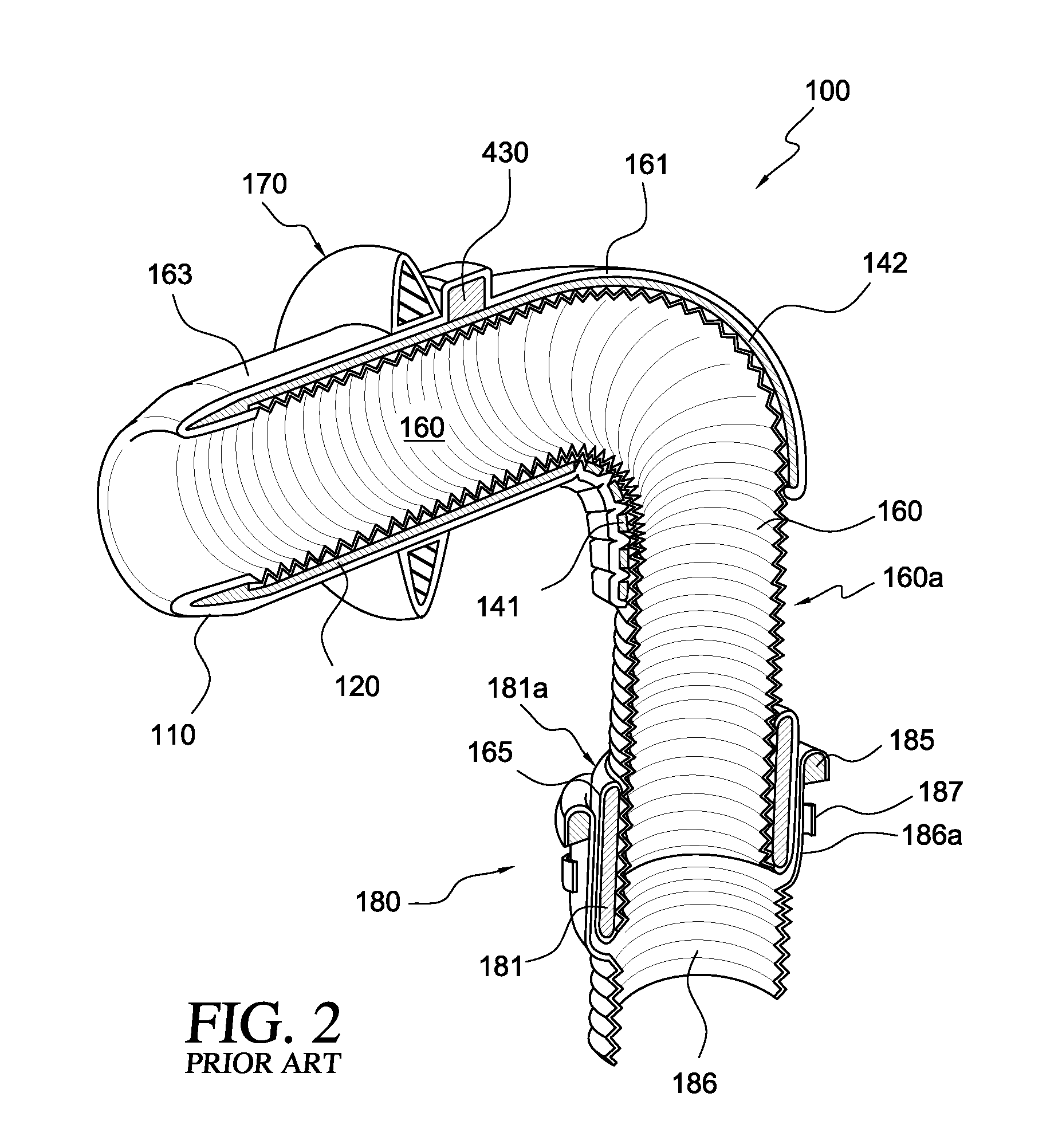
[0049]State 1: After the hole is formed in the wall of the organ by the applicator, three fluid seals are desired, including a fluid seal between the hemostatic connection assembly and the wall of the hollow organ, a fluid seal between the hemostatic connection assembly and the applicator, and an occlusion to prevent fluid loss through the applicator itself.

Problems solved by technology

The most technically challenging aspect of implanting the apicoaortic conduit is placement of the apical connector, which has historically been performed in a two-step process by first cutting and removing a cylindrical tissue plug from the apex and then inserting the apical connector into the formed hole.
This two-step process creates potential for significant blood loss after the hole is formed and before the apical connector is inserted.
Such devices often have an inlet cannula pre-attached to the body of the device and thus, cannot be preloaded onto the applicator described in the '577 application.
However, with a system such as that disclosed in the '672 patent, a major difficulty is that, during use, the moment that the coring means penetrates the heart wall, the action of the heart will cause blood to enter the enclosure and either fills it if it is evacuated or mixes with the saline if it is prefilled.
In either case, the opacity of the blood or blood saline mixture will obscure further action of the coring means and make accurate placement of the conduit difficult.
In addition, because the heart is beating the flexible enclosure will be in constant pulsatile motion further complicating accurate use of the enclosed tools.
If the enclosure is accidentally breached, for example by a sharp edge of the coring tool or the implant, a large amount blood immediately floods the operating field.
This could result in significantly negative outcomes, including death, for the patient.

Method used


Image

  • Applicator, assembly, and method for connecting an inlet conduit to a hollow organ
  • Applicator, assembly, and method for connecting an inlet conduit to a hollow organ
  • Applicator, assembly, and method for connecting an inlet conduit to a hollow organ

Examples


Embodiment Construction

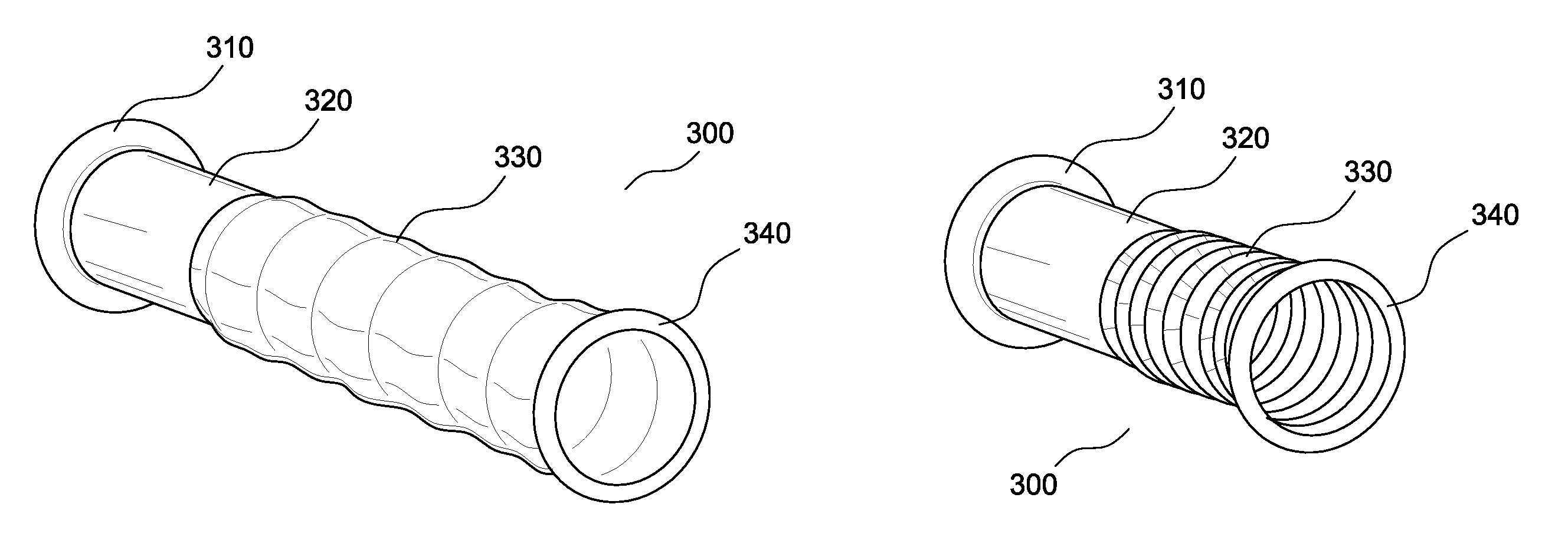
[0070]Referring now to the figures, FIGS. 3A and 3B illustrate an exemplary hemostatic connection assembly of the invention. Hemostatic connection assembly 300 preferably comprises an organ wall connection portion 310 adapted to connect to a wall of a hollow organ, a cuff portion 320, an extension portion 330, and a seal ring portion 340. FIG. 3A shows hemostatic connection assembly 300 with extension portion 330 in an extended state, and FIG. 3B shows hemostatic connection assembly 300 with extension portion 330 in a collapsed or compressed state.

[0071]On one end of hemostatic connection assembly 300, extension portion 330 (which may be referred to as a sewing cuff extension herein) is connected to cuff portion 320 (which may be referred to as a sewing cuff herein). The connection between cuff portion 320 and extension portion 330 is preferably a removable connection. The connection between extension portion 330 and cuff portion 320 may be of any suitable type, such as an adhesive ...


PUM


Abstract

The invention provides an applicator for forming a hole in a wall of a hollow organ and for connecting a hemostatic connection assembly to the hollow organ, wherein, when the hole is formed in the wall of the hollow organ, a first fluid seal exists between the hemostatic connection assembly and the wall of the hollow organ and a second fluid seal exists between the hemostatic connection assembly and the applicator, thereby minimizing fluid loss from the hollow organ. The invention further provides a hemostatic connection assembly for connecting an inlet conduit to a hollow organ, the hemostatic connection assembly comprising a organ wall connection portion, a cuff portion, an extension portion, and a seal ring portion, wherein, during the process of connecting the inlet conduit to the hollow organ, a first fluid seal exists between the organ wall connection portion and the wall of the hollow organ, and a second fluid seal exists between the hemostatic connection assembly and the inlet conduit, thereby minimizing fluid loss from the hollow organ. A method is also disclosed in which the applicator and hemostatic connection assemblies of the invention are used to connect an inlet conduit to a hollow organ.

Description

RELATED APPLICATION DATA[0001]This application claims priority of U.S. Provisional Application Ser. No. 60 / 974,893, filed Sep. 25, 2007, which is hereby incorporated by reference in its entirety.BACKGROUND OF THE INVENTION[0002]1. Field of the Invention[0003]The present invention relates to an applicator, assembly, and method for connecting an inlet conduit to a hollow organ, and more particularly, to a hemostatic connection assembly and inlet conduit connectable to the apex of a heart.[0004]2. Description of the Related Art[0005]As the average age of the United States population increases, so do the instances of aortic stenosis. An alternative approach to the conventional surgical replacement of the stenotic aortic valve involves the use of an apicoaortic conduit. In this approach, the native aortic valve is not removed, and a prosthetic valve is implanted in a parallel flow arrangement. A connection conduit (or tube) connects the apex of the heart to the descending aorta. Somewher...

Claims


Application Information

Patent Timeline
Patent Type & Authority Patents(United States)
IPC IPC(8): A61F2/04
CPCA61B17/11A61B17/3468A61B17/0293A61B17/32A61B17/3423A61B17/320016A61B17/32053A61B2017/00252A61B2017/1107
Inventor BEANE, RICHARD M.BROWN, JOHN W.CRUNKLETON, JAMES ALANGAMMIE, JAMES S.SMITH, JOSEPH L.
Owner CORREX
Learn More