
Method of forming fluid impermeable plug in a subterranean formation

a subterranean formation and impermeable plug technology, applied in the direction of sealing/packing, wellbore/well accessories, chemistry apparatus and processes, etc., can solve the problems of increasing the cost of well operation, reducing hydrocarbon production, and excessive water production, so as to minimize fluid loss

Active Publication Date: 2018-01-16
BAKER HUGHES INC
View PDF43 Cites 1 Cited by
  • Summary
  • Abstract
  • Description
  • Claims
  • Application Information

AI Technical Summary

Benefits of technology

[0008]The invention relates to a method of minimizing fluid loss to porous underground reservoirs or annular space by pumping into the reservoir or a void a crosslinkable fluid comprising a low molecular weight polyacrylamide and a multi-aldehyde crosslinking agent and forming a fluid impermeable reaction product from the polyacrylamide and crosslinking agent. At shallower depths, the temperatures are typically between from about 80° F. to about 150° F.
[0010]In another embodiment, a method is provided for reducing fluid loss to a porous subterranean formation by pumping into the wellbore penetrating the formation a crosslinkable fluid comprising a low molecular weight polyacrylamide and a multi-aldehyde crosslinking agent. The reaction product of the polyacrylamide and multi-functional dialdehyde is gelled in the formation to form a fluid impermeable plug.

Problems solved by technology

Excessive water production or a thief zone during the production phase of a subterranean formation penetrated by a well can decrease hydrocarbon production or increase costs of well operations.
Thus, excessive water production has a direct affect on the productivity of the well and increases operating expenditures.
In addition, expenditures are increased due to the need for disposal of produced water in an environmentally safe manner.
However, chromium based crosslinkers are not allowed in some areas due to environmental regulations.

Method used


Image

  • Method of forming fluid impermeable plug in a subterranean formation
  • Method of forming fluid impermeable plug in a subterranean formation

Examples


example 1

[0033]To 500 cc tap water was added, with stirring at 1000 rpm in an overhead stirrer / paddle combination, 25 g of a partially hydrolyzed low molecular weight (about 500,000) polyacrylamide powder having a percent hydrolysis of about 5 to 6 mole percent. This resulted in a 5% by wt. of polymer in tap water. To 200 cc of the polymer solution prepared was then added a 0.8 cc of a 40% solution of glyoxal and the solution was mixed for 1 min in an overhead stirrer. The solution was then transferred to oven or water bath set at different temperatures. The samples were monitored visually at specified times and a gel code was assigned based on the gel code classification set forth in Table I:

[0034]

TABLE IGelCodeGel BehaviorDescriptionANo gelAppears to have same viscosity aspolymer solutionBHighlyAppears to have slightly higherflowing gelviscosity than polymer solutionCFlowing gelMost of the detectable gel flowsto the cap when bottle invertedDModeratelyA gel portion (5-15%) does notflowing g...

example 2

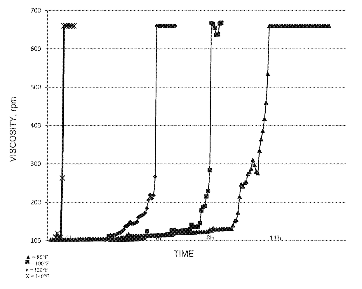
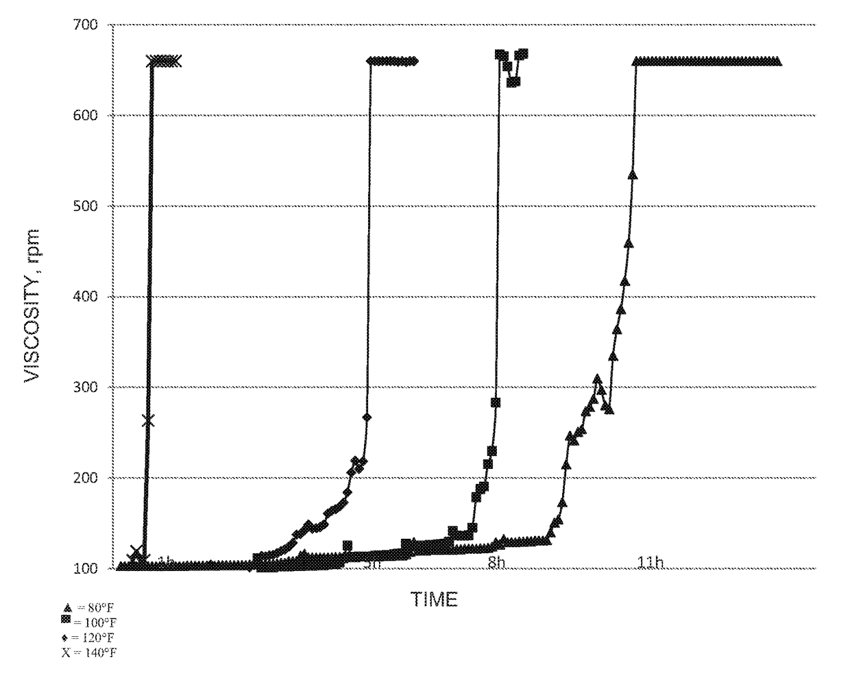
[0037]About 25 g of the same partially hydrolyzed polyacrylamide as Example 1 was added to 500 cc tap water with stirring at 1000 rpm in an overhead stirrer / paddle combination followed by addition of 0.8 cc of a 40% solution of glyoxal. The mixture was then placed in the viscometer and the viscosity of the mixture was monitored at 1 rpm in every 3 minute intervals using a Brookfield LDV-III Viscometer equipped with a #3 LV CYL cylindrical spindle (Brookfield Engineering Laboratories, Middleboro, Mass.) and pump times were determined at 80° F., 100° F., 120° F. and 140° F., as illustrated in FIG. 1 which shows the initial increase in viscosity of the gels due to crosslinking as the gel strength increases from A (initial) to D (moderately flowing gel).


PUM

PropertyMeasurementUnit
temperatureaaaaaaaaaa
time periodaaaaaaaaaa
temperatureaaaaaaaaaa

Abstract

Water and gas flow into a subterranean reservoir may be reduced by pumping into the reservoir a multi-aldehyde crosslinking agent and a low molecular weight polyacrylamide capable of crosslinking with the crosslinking agent. The reaction product forms a gel plug impermeable to water and gas.

Description

[0001]This application claims the benefit of U.S. patent application Ser. No. 61 / 718,180 filed on Oct. 24, 2012.FIELD OF THE INVENTION[0002]Water and gas flow through a high permeability channel in a subterranean reservoir and / or in an annular void space is reduced or stopped by pumping into the reservoir and / or void space a system comprising a low molecular weight polyacrylamide and a multi-aldehyde crosslinking agent.BACKGROUND OF THE INVENTION[0003]Excessive water production or a thief zone during the production phase of a subterranean formation penetrated by a well can decrease hydrocarbon production or increase costs of well operations. The amount of oil and / or gas that may be ultimately recovered from the well is decreased since the water takes the place of other fluids that may flow or be lifted from the well. Thus, excessive water production has a direct affect on the productivity of the well and increases operating expenditures. In addition, expenditures are increased due t...

Claims


Application Information

Patent Timeline
Patent Type & Authority Patents(United States)
IPC IPC(8): E21B33/13C09K8/588C09K8/42C09K8/50E21B33/138C09K8/512
CPCC09K8/426C09K8/50E21B33/138C09K8/588C09K8/512
Inventor BHADURI, SUMIT
Owner BAKER HUGHES INC
Learn More