Liquid crystal display screen

a liquid crystal display and display screen technology, applied in the field of liquid crystal display screens, can solve the problems of increasing the thickness the complexity of the structure of the liquid crystal display

Active Publication Date: 2013-04-09
BEIJING FUNATE INNOVATION TECH
View PDF15 Cites 8 Cited by
  • Summary
  • Abstract
  • Description
  • Claims
  • Application Information

AI Technical Summary

Benefits of technology

[0060]According to the above descriptions, in the liquid crystal display screens, the touch panels and the liquid crystal display panels cooperatively use a common substrate. Thus, the liquid crystal display screens can omit one element and still maintain the same functions. The structures of the liquid crystal display screens can be simplified. The thicknesses of the liquid crystal display screens can be decreased. The utilization efficiencies of the liquid crystal display screens can be improved, and a quality of the liquid crystal display screens can also be improved.

Problems solved by technology

However, the resistance-type touch panel equipped in the liquid crystal display can increase a thickness of the liquid crystal display.
Thus, a structure of the liquid crystal display can be complicated.

Method used


Image

  • Liquid crystal display screen
  • Liquid crystal display screen
  • Liquid crystal display screen

Examples


Embodiment Construction

[0017]The disclosure is illustrated by way of example and not by way of limitation in the figures of the accompanying drawings. It should be noted that references to “an” or “one” embodiment in this disclosure are not necessarily to the same embodiment, and such references mean at least one.

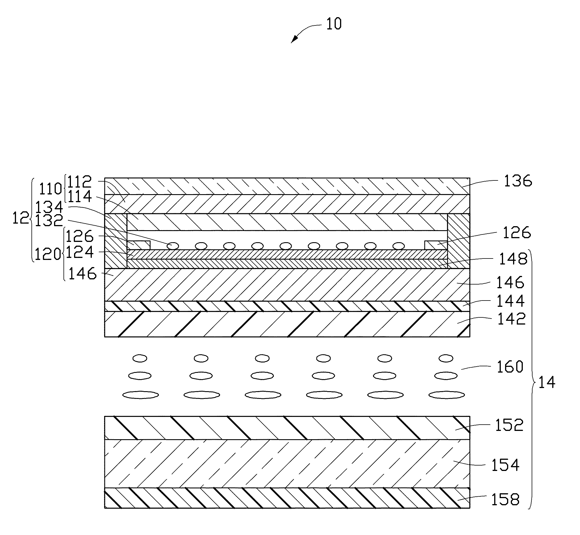
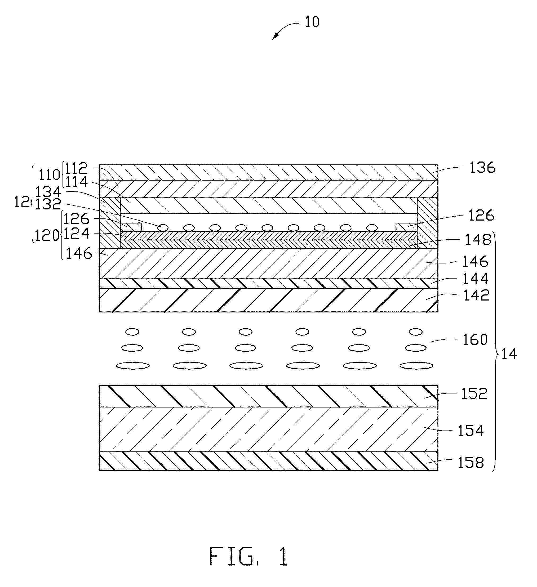
[0018]Referring to FIG. 1, one embodiment of a liquid crystal display screen 10 is provided. The liquid crystal display screen 10 can include a resistance-type touch panel 12 and a liquid crystal display panel 14.

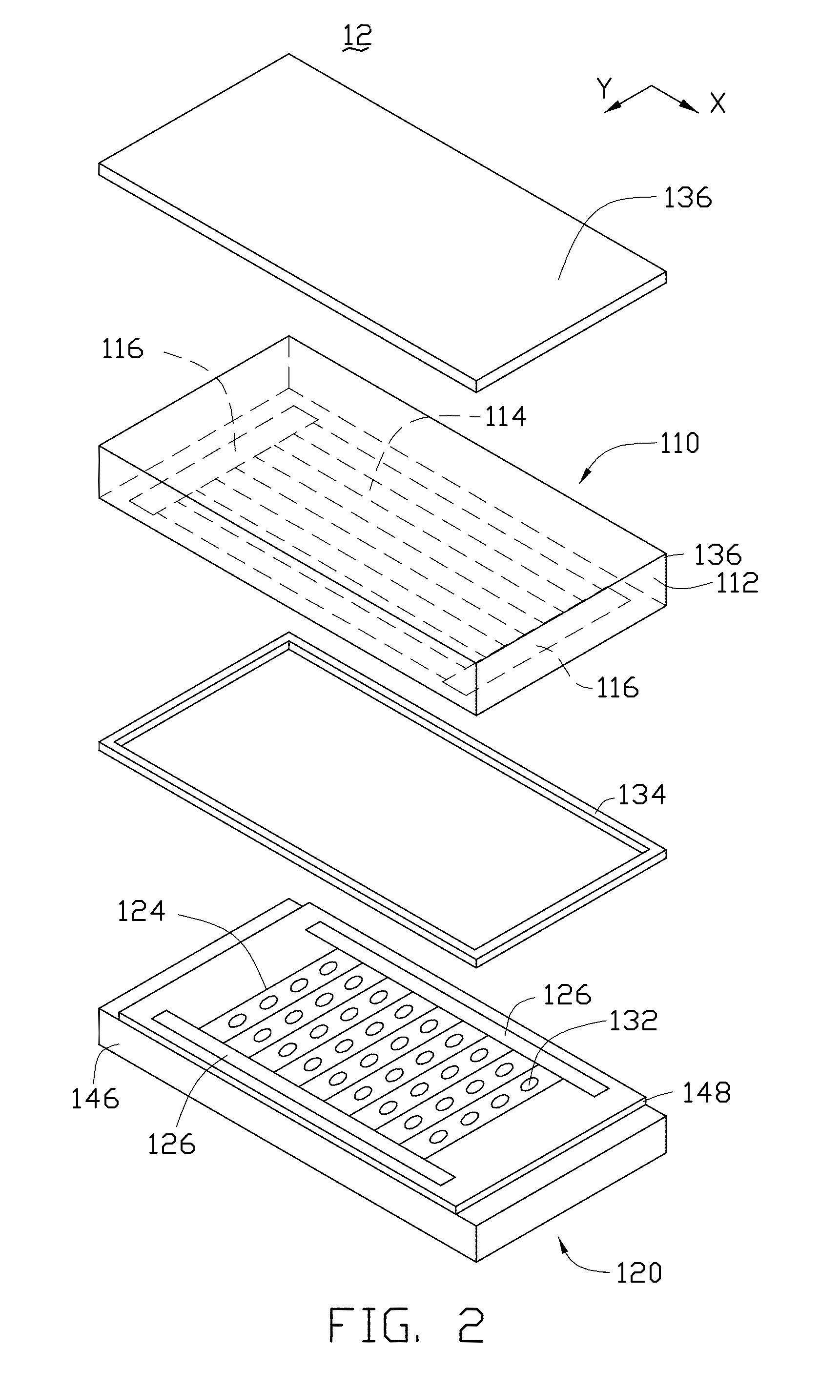
[0019]The touch panel 12 can be a four-line resistance-type touch panel, a five-line resistance-type touch panel, a seven-line resistance-type touch panel, or an eight-line resistance-type touch panel.

[0020]Referring to FIG. 2, one embodiment of the touch panel 12 is the four-line resistance-type touch panel. The touch panel 12 includes a first electrode plate 110, a second electrode plate 120 facing the first electrode plate 110, a plurality of dot spacers 132, an insulated frame 134, a...


PUM

PropertyMeasurementUnit
thicknessaaaaaaaaaa
thicknessaaaaaaaaaa
transparencyaaaaaaaaaa

Abstract

A liquid crystal display screen includes a resistance-type touch panel and a liquid crystal display panel. The touch panel includes a first electrode plate and a second electrode plate opposite to the first electrode plate. The first electrode plate includes a first substrate and a first transparent conductive layer located on the first substrate. The second electrode plate includes a common substrate and a second transparent conductive layer. The liquid crystal display panel includes an upper optical polarizer, an upper substrate, an upper electrode, an upper alignment layer, a liquid crystal layer, a lower alignment layer, a thin film transistor panel, and a lower optical polarizer, from top to bottom in sequence. The upper substrate is the same with the common substrate. The upper optical polarizer is sandwiched between the second transparent conductive layer and the common substrate.

Description

RELATED APPLICATIONS[0001]This application claims all benefits accruing under 35 U.S.C. §119 from China Patent Application No. 201010189984.4, filed on Jun. 2, 2010 in the China Intellectual Property Office, the disclosure of which is incorporated herein by reference.BACKGROUND[0002]1. Technical Field[0003]The present disclosure relates to liquid crystal display screens and, in particular, to a liquid crystal display screen having a touch panel.[0004]2. Discussion of Related Art[0005]A liquid crystal display equipped with a resistance-type touch panel includes a resistance-type touch panel, an upper optical polarizer, an upper substrate, an upper alignment layer, a liquid crystal layer, a lower alignment layer, a thin-film transistor panel, and a lower optical polarizer in sequence. The resistance-type touch panel includes a first electrode plate, a second electrode plate, and a plurality of dot spacers located between the first electrode plate and the second electrode plate. The fi...

Claims


Application Information

Patent Timeline
Patent Type & Authority Patents(United States)
IPC IPC(8): G02F1/1335
CPCG02F1/13338G06F3/0412G06F3/045
Inventor LIU, LIANGFENG, CHENQIAN, LI
Owner BEIJING FUNATE INNOVATION TECH
Why Eureka
Try Eureka